Main power supply awakening device of electric automobile
A wake-up device, electric vehicle technology, applied in electric vehicles, battery circuit devices, circuit devices, etc., can solve the problems of increasing the load and fuel consumption of the car, the trouble of supplementing electric energy, and the volume occupied by the battery, so as to reduce production costs and wake up quickly. , the effect of simple circuit structure
- Summary
- Abstract
- Description
- Claims
- Application Information
AI Technical Summary
Problems solved by technology
Method used
Image
Examples
Embodiment 1
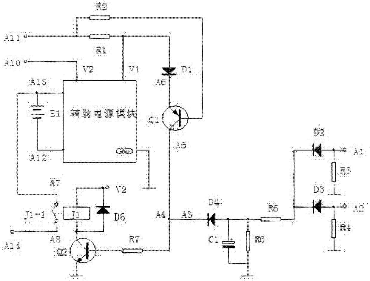
[0053] Such as figure 2 As shown, in this embodiment, the startup module includes a third resistor R3, a fourth resistor R4, a fifth resistor R5, a sixth resistor R6, a second diode D2, a third diode D3, a fourth diode D4 and the first capacitor C1, the anode of the second diode D2 is used as the first input terminal A1 of the startup module, the anode of the third diode D3 is used as the second input terminal A2 of the startup module, the first The negative poles of the second diode D2 and the third diode D3 are connected, and the common contact of the two is connected in series with the fifth resistor R5 and then connected to the positive pole of the fourth diode D4, and the negative pole of the fourth diode D4 As the high-level output terminal A3 of the startup module; the anode of the first capacitor C1 is connected to the anode of the fourth diode D4, the cathode of the first capacitor C1 is grounded, and the fifth resistor R5 is connected to the first The capacitor C1 ...
Embodiment 2
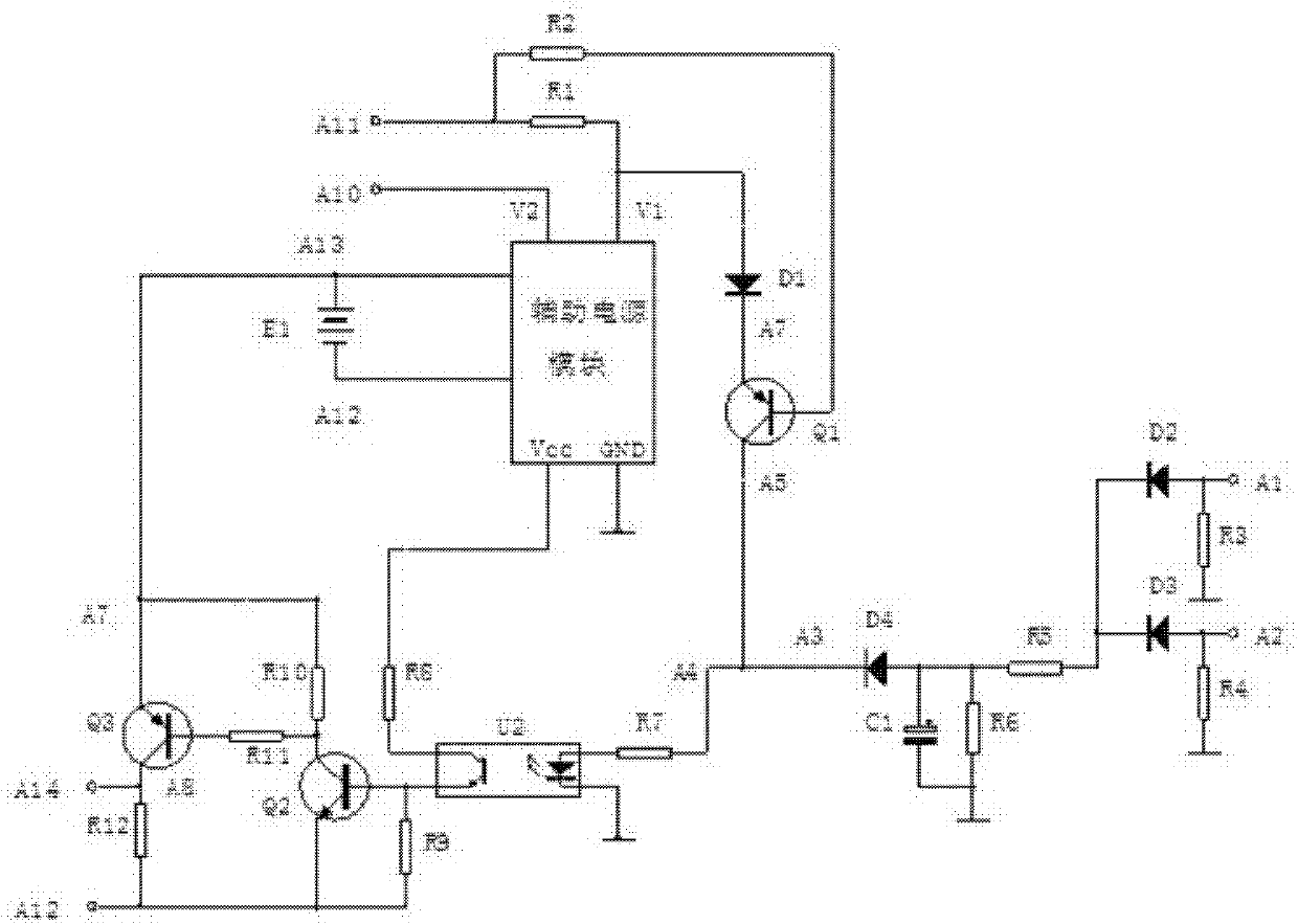
[0062] Such as image 3 As shown, in this embodiment, the starting module and the action module are the same as the first embodiment, the difference is that the enabling module adopts other components, and the enabling module of this embodiment includes a seventh resistor R7, an eighth resistor R8, The ninth resistor R9, the tenth resistor R10, the eleventh resistor R11, the twelfth resistor R12, the second transistor Q2, the third transistor Q3 and the photocoupler U2, the light emitting device of the photocoupler U2 The positive pole of the seventh resistor R7 is connected to one end of the seventh resistor R7, the other end of the seventh resistor R7 is used as the high-level input terminal A4 of the enable module, the negative pole of the light-emitting device of the photocoupler U2 is grounded, and the light of the photocoupler U2 The collector of the receiving device is connected to the power supply terminal VCC of the auxiliary power supply module through the eighth res...
Embodiment 3
[0065] Such as Figure 4 As shown, in this embodiment, the starting module, auxiliary power module and enabling module are the same as those in Embodiment 2, the difference is that the action module has changed, and the action module in this embodiment includes a first resistor R1, a second resistor R2, The thirteenth resistor R13, the fourteenth resistor R14, the fifth diode D5 and the comparator U1, one end of the first resistor R1 is connected with one end of the second resistor R2 to form a common contact, which is used as the action module The second output terminal A11; the other end of the first resistor R1 is connected to the first voltage output terminal V1 of the auxiliary power module; the other end of the second resistor R2 is connected to the inverting terminal of the comparator U1, and the comparator U1 The non-inverting terminal of the comparator U1 is connected to the first voltage output terminal V1 of the auxiliary power supply module through the thirteenth r...
PUM
 Abstract
Description
Claims
Application Information
 - R&D
- Intellectual Property
- Life Sciences
- Materials
- Tech Scout
- Unparalleled Data Quality
- Higher Quality Content
- 60% Fewer Hallucinations
Browse by: Latest US Patents, China's latest patents, Technical Efficacy Thesaurus, Application Domain, Technology Topic, Popular Technical Reports.
© 2025 PatSnap. All rights reserved.Legal|Privacy policy|Modern Slavery Act Transparency Statement|Sitemap|About US| Contact US: help@patsnap.com


