Sea surface oil spilling segmentation method based on polarized SAR (synthetic aperture radar) data fusion

A sea oil spill and data technology, applied to instruments, character and pattern recognition, computer components, etc., can solve the problem of SAR image not being universal

Inactive Publication Date: 2014-04-16
TSINGHUA UNIV +1
View PDF3 Cites 0 Cited by
  • Summary
  • Abstract
  • Description
  • Claims
  • Application Information

AI Technical Summary

Problems solved by technology

[0005] The object of the present invention is to provide a sea surface oil spill image segmentation method based on active contour model-based polarimetric SAR data fusion, to solve the problem that the regional statistical model based on additive noise is not universal to SAR images and polarimetric SAR images At the same time, the present invention can effectively integrate different SAR data sources and realize the automatic segmentation of sea oil spills

Method used


Image

  • Sea surface oil spilling segmentation method based on polarized SAR (synthetic aperture radar) data fusion
  • Sea surface oil spilling segmentation method based on polarized SAR (synthetic aperture radar) data fusion
  • Sea surface oil spilling segmentation method based on polarized SAR (synthetic aperture radar) data fusion

Examples


Embodiment 1

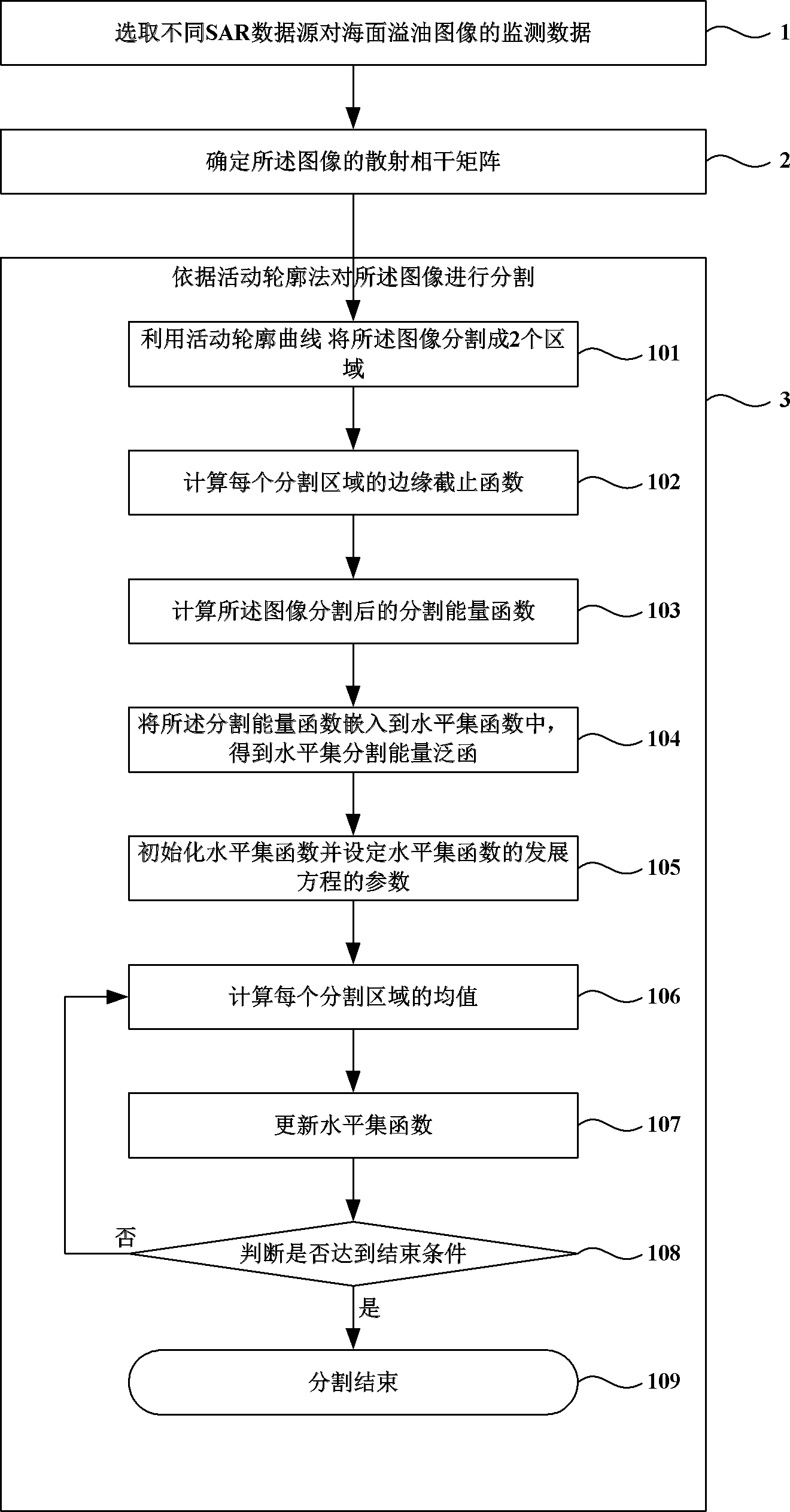
[0048] figure 1 It is a flowchart of a sea surface oil spill segmentation method based on polarization SAR data fusion. figure 1 Among them, the sea surface oil spill segmentation method based on polarization SAR data fusion provided by the present invention includes:

[0049] Step 1: Select the sea surface oil spill image monitoring data from different synthetic aperture radar data sources.

[0050] Step 2: Determine the scattering coherence matrix of the image.

[0051] Synthetic Aperture Radar (SAR) emits an electromagnetic wave, and the measured value of the target observation is included in the radar backscattered wave. Due to the influence of speckle noise (Speckle), the single-view SAR intensity image obeys a negative exponential distribution. The multi-view SAR intensity image σ obeys the Gamma distribution, denoted as G(·) is the Gamma function, and there is

[0052] P ( σ ) = ( L u I ) L 1 Γ ( L ) σ L - 1 exp ...

Embodiment 2

[0105] The following describes the implementation process of the present invention with an actual sea surface oil spill image simulation data.

[0106] Step 201: figure 2 The total power map of the simulated oil film data is given. The size of the image is 571×421. The backscattering coefficients of the sea surface and the oil film are respectively

[0107] [|S HH | 2 2|S HV | 2 |S VV | 2 ] oil =[0.0031 5.3598×10 -4 0.0047]

[0108] (1)

[0109] [|S HH | 2 2|S HV | 2 |S VV | 2 ] sea =[0.0048 5.7513×10 -4 0.0093]

[0110] The shape of the oil film in this simulation image is selected from the oil spill shape obtained by the real ASAR sensor. For the specific oil spill shape, see image 3 Shown. In this case, the data sources used are three sets of single-polarization SAR intensity data, HH | 2 , |S HV | 2 And |S VV | 2 ; Two sets of intensity fusion data of dual-polarization SAR observation modes, |S HH | 2 +|S ...


PUM


Abstract

The invention discloses a sea surface oil spilling segmentation method based on polarized SAR (synthetic aperture radar) data fusion and belongs to the technical field of the application of an SAR to marine remote sensing. The sea surface oil spilling cutting method based on polarized SAR data fusion comprises the following steps: establishing an active contour energy functional based on a segmentation region maximum posterior probability standard, representing the distribution of the segmentation region into a Gibbs prior probability model, embedding an active contour model into a high-dimensional level set function, and obtaining a development equation by using an Euler Lagrange formula, wherein the model comprises a CFAR edge detection weighted boundary length item and a CFAR edge detection weighted fusion data statistics distance item. In addition, the invention provides a method for determining an evolution parameter. The segmentation result is obtained according to the level set function of the oil film attenuation characteristic initialization through evolution of the equation. Various SAR data and polarized SAR data can be fused effectively, and the automatic segmentation of the dark region of the sea surface can be realized.

Description

Technical field [0001] The invention belongs to the technical field of synthetic aperture radar (SAR) marine remote sensing applications, and particularly relates to a sea surface oil spill segmentation method based on polarization SAR data fusion. Background technique [0002] As people's activities on the sea become more frequent, oil slick on the sea has become an important environmental pollution problem that people are increasingly concerned about. At present, marine oil spill pollution is mainly caused by two factors. One is pollution caused by major accidents, such as oil tanker accidents and oil spills on oil and gas field platforms; the other is caused by illegal discharge of oil tankers during transportation. Since the satellite system can provide continuous ocean surface monitoring data and can conduct a wide range of surveying and mapping, it is very suitable for monitoring the ocean. There are many remote sensing methods for monitoring sea conditions: optical, infra...

Claims


Application Information

Patent Timeline
Patent Type & Authority Patents(China)
IPC IPC(8): G06K9/46
Inventor 殷君君杨健张庆君李延齐亚琳
Owner TSINGHUA UNIV
Why Eureka
Try Eureka