
Optical display panel, panel display module and shading structure forming method

A technology of optical display panel and shading structure, which is applied in optics, nonlinear optics, instruments, etc., can solve the problems of weakened effect, narrowed frame width design, light spillage, etc., and achieves the degree of suppressing light leakage, reducing the intensity, and simplifying the setting. Effect

Inactive Publication Date: 2012-07-25
AU OPTRONICS CORP
View PDF7 Cites 20 Cited by
  • Summary
  • Abstract
  • Description
  • Claims
  • Application Information

AI Technical Summary

Problems solved by technology

Generally speaking, the light-shielding tape needs to be aligned with the polarizer, but the side length of the LCD panel is not short, which makes it difficult to align when manually attaching the light-shielding tape. gap
The overlapping phenomenon may cause poor combination of other components, and the gap is likely to have light leaking from here
Therefore, at present, the liquid crystal panel mostly uses the external structural frame to assist in covering the edge of the liquid crystal panel, so as to shield the light leaked from the light-shielding tape again, in an attempt to reduce the impact of light leakage on the user, but this will make it difficult to shrink the screen frame. Screen specifications are becoming more and more stringent. Whether it is the expansion of the display area or the reduction of the size of the device, the frame width design will be reduced accordingly, and the effect of using the structural frame to assist in shading will tend to weaken. The problem of light leakage caused by manually attaching tapes is still difficult to overcome

Method used


Image

  • Optical display panel, panel display module and shading structure forming method
  • Optical display panel, panel display module and shading structure forming method
  • Optical display panel, panel display module and shading structure forming method

Examples


Embodiment Construction

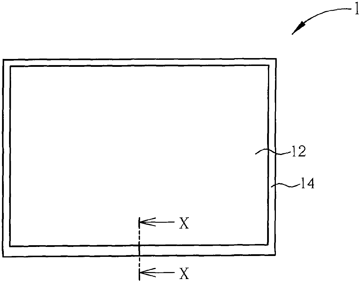
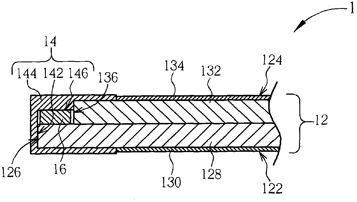
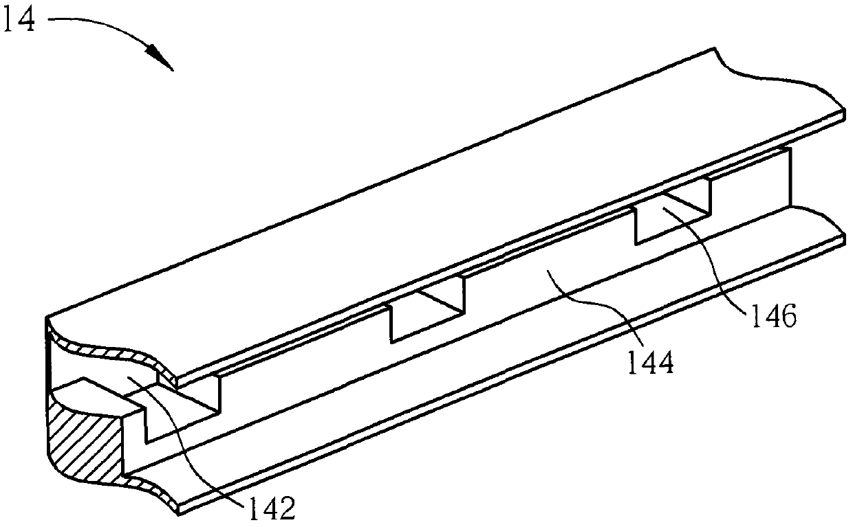
[0036] see figure 1 and figure 2 , figure 1 It is a top view of an optical display panel 1 according to a preferred embodiment of the present invention, figure 2 for the optical display panel 1 along figure 1 Partial sectional view of midline X-X. The optical display panel 1 comprises an optical multilayer structure 12, a plurality of shading elements 14 and a plurality of control chips 16 (in figure 2 only one of them is shown in ). The four sides of the optical multilayer structure 12 are covered with light shielding elements 14 , and the control chip 16 is disposed on one or more of the sides. The light leakage phenomenon of the optical display panel 1 can be effectively suppressed by utilizing the shielding and anti-reflection effect of the light-shielding member 14 .

[0037] Further, the optical multilayer structure 12 has a light incident side 122 , a light exit side 124 opposite to the light incident side 122 , and a side 126 adjacent to the light incident sid...


PUM


Abstract

The invention discloses an optical display panel, a panel display module with the optical display panel, and a shading structure forming method for the optical display panel. The optical display panel comprises an optical multilayer structure and a light shielding member. The optical multilayer structure comprises a light incident side, a light exiting side relative to the light incident side, and a lateral edge side arranged between the light incident side and the light exiting side. The light shielding member is provided with a reflection suppressing surface. The light shielding member continuously sticks to the light incidence side.

Description

technical field [0001] The present invention relates to an optical display panel, a panel display module and a method for forming a light-shielding structure, in particular to an optical display panel with a light-shielding structure on the side, a panel display module with the optical display panel, and a light-shielding structure for the optical display panel method of structure formation. Background technique [0002] The liquid crystal display screen has become a mainstream display device. The backlight of the liquid crystal display screen is mainly provided by a backlight module to selectively pass through the liquid crystal panel to achieve the function of image display. The liquid crystal panel is an optical multilayer structure. In a normal display mechanism, the light provided by the backlight module should completely pass through the optical multilayer structure. More or less some light rays go out of the liquid crystal panel through a non-predetermined path, resu...

Claims


Application Information

Patent Timeline
IPC IPC(8): G02F1/13G02F1/1335
Inventor 陈南叡
Owner AU OPTRONICS CORP
Learn More