
Nanomanipulator

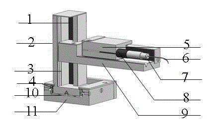
A nano-manipulator and manipulator technology, applied in the field of nano-manipulators, can solve the problems of complex structure, small movement scale and large size of nano-manipulators, and achieve the effects of increasing the range of motion, small elongation range and reducing volume

Inactive Publication Date: 2013-06-12
LANZHOU UNIVERSITY
View PDF3 Cites 2 Cited by
  • Summary
  • Abstract
  • Description
  • Claims
  • Application Information

AI Technical Summary

Problems solved by technology

[0003] At present, nanomanipulators mainly adopt piezoelectric ceramic drive technology. Piezoelectric ceramic drive has the disadvantage of hysteresis / non-linear characteristics, and its displacement output is related to the turning point of the input voltage and the applied voltage.
Existing nanomanipulators based on piezoelectric ceramic drive technology have disadvantages such as complex structure, relatively large size, small motion scale, large drift, and inability to truly achieve linear motion.
Therefore, it is an important direction to study small-sized, high-precision driven new nanomanipulators based on piezoelectric ceramic drive technology for the above shortcomings. At present, such research in China is still blank.

Method used


Image

  • Nanomanipulator

Examples


Embodiment Construction

[0023] The present invention will be further described below in conjunction with the accompanying drawings and embodiments.

[0024] Such as figure 1 As shown, the nanomanipulator includes a positioning device and an actuator. The positioning device includes a moving track, a piezoelectric ceramic, and a moving table. The piezoelectric ceramic is installed in the moving track, and a pulse voltage is applied to the piezoelectric ceramic to drive the motion. The frictional contact of the table moves along the motion track; the actuator is connected with the motion table, and the actuator is the manipulator; the pulse period of the pulse voltage is equal to the telescopic period of the piezoelectric ceramic; the three positioning devices are vertically combined together , which are X-axis positioning device, Y-axis positioning device, and Z-axis positioning device respectively; there is a thin aluminum oxide sheet in the moving track; a small track is arranged in the moving trac...


PUM


Abstract

The invention belongs to the field of nanomanipulators, in particular to a nanomanipulator driven by piezoelectric ceramic. The nanomanipulator comprises a positioned and an executing mechanism. The positioned comprises a motional track, piezoelectric ceramic and a movement table. The piezoelectric ceramic is installed in the motional track and an impulse voltage is applied to the piezoelectric ceramic to drive the movement table to move along the motional track in a frictional and contacted manner. The executing mechanism is connected with movement table and the executing mechanism is a manipulating arm. The nanomanipulator is symmetrical in structure, good in balance and compact in dimension, moves linearly, and further reduces the internal stress and counteracts deformation caused by temperature to a certain extent, and can be widely applied to precisely monitoring, cutting and assembling nano single bodies and measuring the physical properties of the nano single bodies.

Description

technical field [0001] The invention belongs to the field of nano manipulators, in particular to a nano manipulator driven by piezoelectric ceramics. Background technique [0002] In recent years, the application of electron microscope in situ nanomanipulators in materials science, especially nanotechnology, has become increasingly important, and its research and development has received great attention. Electron microscope in-situ nanomanipulators are mainly used for the manipulation, tailoring, splicing, and in-situ physical property measurement of nanometer monomers at the micro / nanometer scale. In order to make the nanomanipulator work stably and efficiently, the required technical components include braking, measurement, system design and manufacturing, calibration, control, signal transmission and human-machine communication. Electron microscope in situ nanomanipulators mainly include scanning electron microscope in situ nanomanipulators (referred to as scanning elect...

Claims


Application Information

Patent Timeline
Patent Type & Authority Patents(China)
IPC IPC(8): G01Q10/00
Inventor 彭勇张军伟金斌玲谢凤珍张宏马鸿斌齐阔马传生张俊丽薛德胜
Owner LANZHOU UNIVERSITY
Learn More