Dynamic compensation mechanism for bottom dead center of high-speed precise press

A dynamic compensation and press technology, applied in the field of presses, can solve the problems of difficult to achieve bottom dead center dynamic compensation, affecting the quality of stamping parts, die life, thread failure, etc., to improve quality and die life, large bearing capacity, friction Low resistance effect

Inactive Publication Date: 2012-07-25
JIANGSU XUZHOU METALFORMING MACHINE GROUP
View PDF6 Cites 7 Cited by
  • Summary
  • Abstract
  • Description
  • Claims
  • Application Information

AI Technical Summary

Problems solved by technology

[0003] In the prior art, the dynamic compensation of the bottom dead center of the slider is realized by fine-tuning the mold height, which requires the motor to have a high response characteristic, and the adjustment is made when avoiding the stamping area. At this time, the thread of the mold height adjustment part of the slider It needs to be loosened, and it needs to be locked again after the adjustment is completed; the thread of the adjusted part bears the punching force, and repeated adjustments will easily lead to thread failure, and it is difficult to realize the dynamic compensation of the bottom dead point, which will directly affect the quality of the stamping part and the life of the die

Method used


Image

  • Dynamic compensation mechanism for bottom dead center of high-speed precise press
  • Dynamic compensation mechanism for bottom dead center of high-speed precise press
  • Dynamic compensation mechanism for bottom dead center of high-speed precise press

Examples


Embodiment Construction

[0014] The present invention will be further described below in conjunction with accompanying drawing.

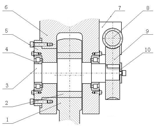
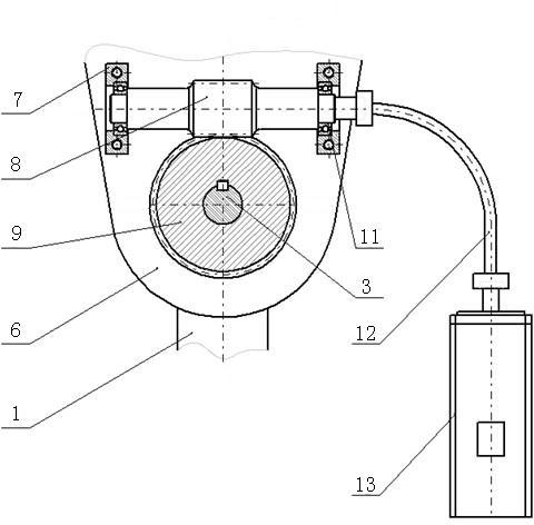
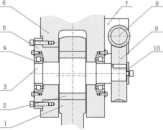
[0015] Such as figure 1 and figure 2 As shown, a dynamic compensation mechanism for the bottom dead point of a high-speed precision press includes a shaft 3 mounted on a connecting rod 6 through two cylindrical roller bearings 4 and a shaft seat 5. The shaft 3 is an eccentric structure in the middle. One end of 3 is equipped with a worm 8 and a worm wheel 9 mechanism, the worm 9 is connected with the shaft 3, the worm 8 is fixed on the connecting rod 6 through the bearing seat 7 and connected with the servo motor 13 through the elastic flexible shaft 12, and the servo motor 13 is fixed on on the press body.

[0016] The eccentric part of the shaft 3 is connected with the central shaft 1 through the central bearing shell 2, and the transmission of the shaft 3 drives the central shaft 1 to rise or fall, and then drives the moving parts of the slider to rise or fall, so as ...


PUM


Abstract

The invention discloses a dynamic compensation mechanism for a bottom dead center of a high-speed precise press, which belongs to the technical field of pressure machinery. The dynamic compensation mechanism comprises a shaft which is installed on a connecting rod through two cylindrical roller bearings and a shaft seat; the shaft is a middle eccentric structure; a worm and worm wheel mechanism is arranged at one end of the shaft; a worm wheel is connected with the shaft; a worm is fastened on the connecting rod through a bearing seat and is connected with a servo motor through an elastic flexible shaft; and the servo motor is fastened on a machine body of the press. The dynamic compensation mechanism has the beneficial effects that: frictional resistance overcome during the dynamic compensation is small through a shaft support mechanism, the bearing capacity is large during the stamping, the assembly is convenient, and threads do not need to be loosened in a die-filling adjusting height of a slide block during the compensation, so that bottom dead center precision deviation of the slide block, caused by gaps among the threads is eliminated, the dynamic compensation of the bottom dead center is realized, the high stamping precision of the press is ensured, the quality of stamped parts is improved, and the service life of a mould is prolonged; at the mean time, the servo motor is directly fastened on the machine body of the press, so that the servo motor is not impacted by vibration, and the reliability of the servo motor is improved.

Description

technical field [0001] The invention relates to a press, in particular to a dynamic compensation mechanism for the bottom dead point of a high-speed precision press, which belongs to the technical field of press machinery. Background technique [0002] In the current forging machinery industry, high-speed precision presses are required to have high bottom dead point accuracy. Traditional high-speed precision presses mostly use a crank slider mechanism, which relies on a motor to drive a worm gear mechanism, thereby driving the screw pair to rotate. , to realize the adjustment of the height of the slide block, the thread pair bears the periodic stamping force during stamping, and the hydraulic system is required to lock the thread to eliminate the thread gap. [0003] In the prior art, the dynamic compensation of the bottom dead center of the slider is realized by fine-tuning the mold height, which requires the motor to have a high response characteristic, and the adjustment ...

Claims


Application Information

Patent Timeline
IPC IPC(8): B30B15/00
Inventor 柯尊芒鹿新建邓建春黄禹
Owner JIANGSU XUZHOU METALFORMING MACHINE GROUP
Why Eureka
Try Eureka