
Electronic intelligent speed regulating control device

A technology of intelligent speed regulation and control devices, which is applied to feeding devices, manufacturing tools, metal processing machinery parts, etc.

Active Publication Date: 2014-01-08
莱州市蔚仪试验器械制造有限公司
View PDF11 Cites 0 Cited by
  • Summary
  • Abstract
  • Description
  • Claims
  • Application Information

AI Technical Summary

Problems solved by technology

The above-mentioned existing control methods cannot meet this requirement

Method used


Image

  • Electronic intelligent speed regulating control device

Examples


Embodiment Construction

[0013] The present invention will be further described below in conjunction with the accompanying drawings and specific embodiments.

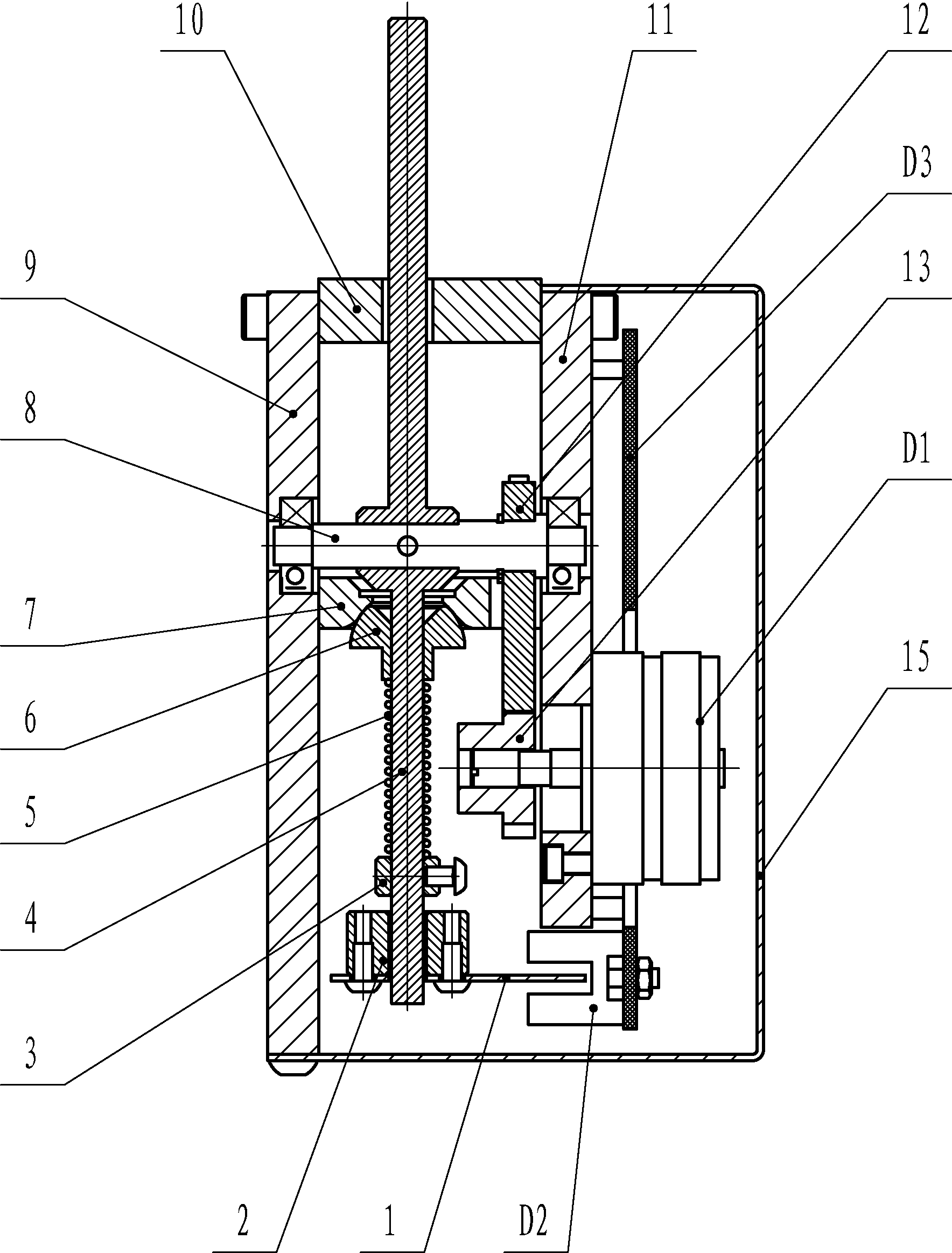
[0014] Such as figure 1 , this embodiment includes a circuit board D3 for connecting with the feed motor of the sample cutting machine, the circuit board D3 is connected with a potentiometer D1, and a photoelectric switch D2 is installed on the circuit board D3. In this embodiment, the potentiometer D1 and the circuit board D3 are installed on the right support plate 11 respectively.

[0015] It also includes a left support plate 9 and a right support plate 11 arranged parallel to each other, and a gear shaft 8 whose left and right ends are respectively installed on the left and right support plates through bearings. The gear shaft 8 is provided with a driving gear 12, and a driven gear 13 meshed with the driving gear 12 is mounted on the shaft end of the potentiometer D1.

[0016] On the said gear shaft 8 is fixedly connected with a steerin...


PUM


Abstract

The invention discloses an electronic intelligent speed regulating control device. A circuit board (D3) is connected with a potentiometer (D1) and a photoelectric switch (D2), a driving gear (12) is arranged on a gear shaft (8), the left end and the right end of the gear shaft (8) are mounted on a left support plate and a right support plate respectively by bearings, a driven gear (13) which is meshed with the driving gear (12) is mounted at a shaft end of the potentiometer (D1), an operating rocker (4) is fixedly connected onto the gear shaft (8), the trend of the operating rocker (4) is perpendicular to the gear shaft (8), and a separating blade (1) matching with the photoelectric switch (D2) is mounted at the lower end of the operating rocker (4). The movement speed of a worktable of a test sample cutting machine is changed along with change of a swinging angle of the operating rocker, and accordingly is automatically regulated in a stepless manner. In addition, advancing and withdrawing of the worktable are controlled to be automatically switched according to judgment of the swinging direction of the operating rocker.

Description

technical field [0001] The invention relates to a forward and reverse control and rotation speed regulating device of a feed motor. It is mainly used on metallographic cutting machines to control the forward and backward conversion of the reciprocating movement of the worktable and the control of the moving speed based on the judgment of the swing direction of the joystick. technical background [0002] When the worktable of the sample cutting machine (such as metallographic sample cutting machine) carries the sample to and fro, the control of the feed motor driving the reciprocating movement of the worktable is mainly realized through the joystick. The existing joystick for controlling the feed motor only plays the role of starting and closing the feed motor, but cannot realize the stepless speed regulation control of the movement of the workbench. [0003] The feed of the sample cutting machine has its special requirements. When the distance between the sample and the saw...

Claims


Application Information

Patent Timeline
Patent Type & Authority Patents(China)
IPC IPC(8): B23Q5/34
Inventor 王耀仪于旭兵滕锡松巩玉亮郑跃军张磊王云鹏
Owner 莱州市蔚仪试验器械制造有限公司
Learn More