
L-wave-band shore-based sea clutter observation system based on vector network analyzer

A vector network analysis and observation system technology, which is applied in the field of L-band shore-based sea clutter observation system, can solve the requirements of increasing signal source complexity and bandwidth internal component stability, sea clutter modeling accuracy is not high, and the system is not enough and other issues, to achieve the effect of coordination work and equipment status monitoring, automatic measurement and effective management, and stable system performance

Active Publication Date: 2012-07-18
THE 22ND RES INST OF CHINA ELECTRONICS TECH GROUP CORP
View PDF3 Cites 16 Cited by
  • Summary
  • Abstract
  • Description
  • Claims
  • Application Information

AI Technical Summary

Problems solved by technology

Domestic sea clutter theory research lacks the support of effective experimental data, and most of them are simulation calculations. The accuracy of sea clutter modeling is not high, and the engineering practicability of the research results is poor.
The experimental measurement includes shore-based measurement and airborne radar measurement. The airborne measurement is limited by the time and place of the measurement, the measurement data samples are small, the measurement results are also very different, and the system is not enough
In view of the lack of observation means, the research work based on the measured data is less, the long-term observation platform of sea clutter based on the shore-based platform and the applicability research of the sea clutter mean model based on the measured data are still in their infancy
Especially in recent years, due to the emergence of stealth targets and low-altitude and ultra-low-altitude penetration, the research of small grazing angle and high-resolution sea clutter has become an important direction, and due to the lack of effective observation methods, small grazing angle, high-resolution Relative lack of sea clutter data
[0004] Depending on the form of the transmitted signal, clutter measurement radars have different systems. The continuous wave is the basic configuration, but the distance cannot be determined because it is not modulated.
Pulse radar determines the distance information by measuring the time delay between the transmitted pulse and the received pulse, but the transmission power is relatively large
The frequency stepping radar uses the signal source to transmit the hopping frequency instead of the sweep mode, which can increase the distance resolution. The disadvantage is that the complexity of the signal source and the stability requirements of the components within the entire bandwidth are increased.
[0005] In addition, the establishment of a shore-based long-term sea clutter observation station can be built on the top of a mountain or on a high platform near the sea, but it involves problems in the implementation of civil engineering, hydropower and other projects, and the construction period is long and the cost is high, so the implementation is relatively difficult
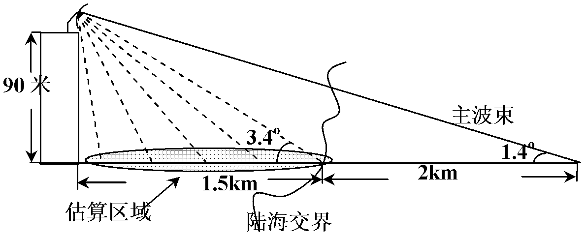
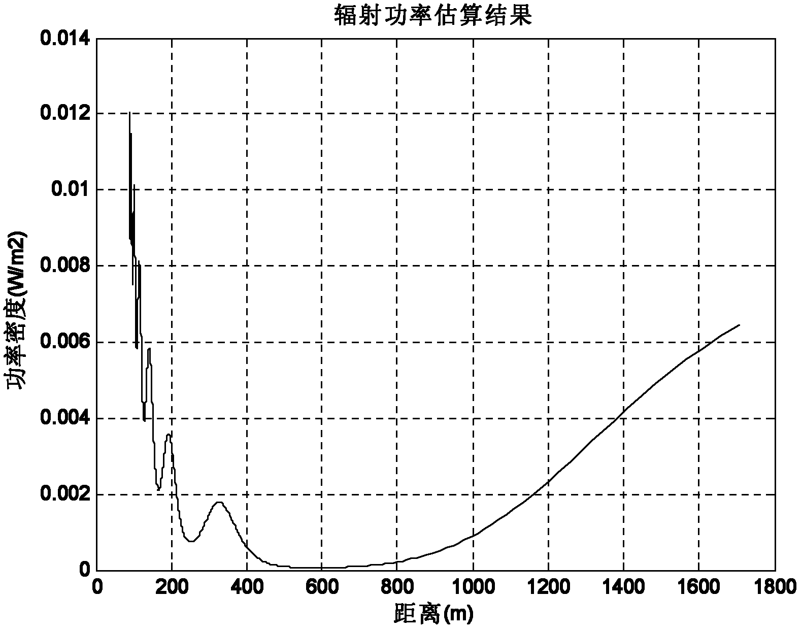
In addition, it can be erected on high-rise buildings near the sea. Through on-the-spot investigations, the roof of a high-rise building with appropriate conditions can be selected as a building platform, which can greatly simplify many problems in project implementation. The disadvantage is that when the radiation power is large, it will cause radiation to the surrounding environment. Pollution

Method used


Image

  • L-wave-band shore-based sea clutter observation system based on vector network analyzer
  • L-wave-band shore-based sea clutter observation system based on vector network analyzer
  • L-wave-band shore-based sea clutter observation system based on vector network analyzer

Examples


Embodiment Construction

[0034] The present invention will be further described in detail below with reference to the accompanying drawings and embodiments. It should be understood that the specific embodiments described herein are only used to illustrate the present invention, but not to limit the present invention.

[0035] The invention utilizes the frequency stepping continuous wave system, adopts a narrow intermediate frequency bandwidth to reduce the noise threshold, improves the dynamic range, reduces the transmission power on the premise of maintaining the long-distance detection performance, and uses the wide frequency hopping waveform to obtain high distance resolution, So as to realize the high-resolution detection of shore-based small rubbing angle.

[0036]The invention is constructed on the basis of vector network, has a built-in signal source, can transmit frequency step continuous wave signals under specified parameters, and has stable performance. The L-band shore-based sea clutter o...


PUM


Abstract

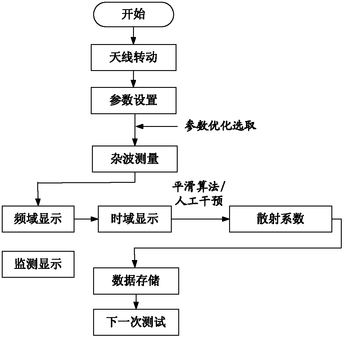
The invention discloses an L-wave-band shore-based sea clutter observation system based on a vector network analyzer. The system comprises the vector network analyzer, a power amplifier, a low noise amplifier, a transmit-receive antenna and a master control computer. The vector network analyzer is transmit-receive signal equipment and is used to emit a frequency-stepping continuous wave signal with a specified parameter under control of the master control computer. After being amplified by the power amplifier, the signal is radiated to a sea area to be measured through the transmit-receive antenna. An echo signal is received by the transmit-receive antenna and enters into the vector network analyzer after a signal-to-clutter ratio is increased through the low noise amplifier. The vector network analyzer is also used to arrange a proper intermediate-frequency bandwidth under the control of the master control computer and carries out time domain windowing, calculation and processing to the echo signal. Sea clutter data can be obtained. By using the technical scheme of the invention, long distance detection can be performed under low radiation power; the detection with a small grazing angle and high resolution can be realized; system performance is stable and an automation degree is high.

Description

technical field [0001] The invention relates to the technical field of radar clutter testing, in particular to an L-band shore-based sea clutter observation system based on a vector network analyzer. Background technique [0002] The background clutter on the sea surface is the main factor that affects and limits the target detection performance of radars, especially low-elevation-angle detection radars, airborne and spaceborne down-looking radars. The sea clutter caused by the abnormal changes of sea surface in the land-sea interface area will greatly increase the false alarm of radar. Understanding sea clutter requires collecting enough measurements under various parameter conditions for in-depth analysis. [0003] In order to develop high-performance radar and improve target detection capabilities, since the 1950s and 1960s, various countries have used vehicle-borne scatterometers, airborne radars and shore-based radar systems to carry out various forms, multi-band and s...

Claims


Application Information

Patent Timeline
Patent Type & Authority Applications(China)
IPC IPC(8): G01S7/02G01S7/41
Inventor 张玉石张浙东李慧明李善斌许心瑜田霞朱秀芹尹志盈
Owner THE 22ND RES INST OF CHINA ELECTRONICS TECH GROUP CORP
Learn More