Device for measuring thermal conductivity of vacuum glass

A technology of vacuum glass and measuring device, applied in the direction of thermal development of materials, etc., can solve the problems of unreachable detection board, lack of accuracy of detection result data, bad top, etc., to improve reliability and accuracy, improve reliability and easy operation. performance, reducing production costs

Inactive Publication Date: 2014-02-19
SHAANXI UNIV OF SCI & TECH
View PDF2 Cites 2 Cited by
  • Summary
  • Abstract
  • Description
  • Claims
  • Application Information

AI Technical Summary

Problems solved by technology

[0013] Although the above two factors have been considered in the design of some vacuum glass thermal conductivity meters at present, for C 测 parameters, but in the structural design, the detection condition of constant pressure is realized by the method of pressure sensor detection and automatic control; and the method of using two parallel detection plates to achieve uniform and good pressure through the up and down mechanical movement of the slideway Contact; this is a very ideal solution in theory, but it has encountered great challenges in actual use
For example, when there are impurities attached to the surface of the hot plate or the upper and lower surfaces of the vacuum glass sample to be tested (this situation is unavoidable objectively in practice), it will cause the detection plate to not be able to achieve uniform and good contact with the glass to be tested, thus Not only does the data of the test result lack accuracy, but also because of the non-deformability of the glass, one of the pressure sensors on the cold plate cannot detect the pressure, which makes the computer make a wrong judgment, so that it instructs the motor to drag the cold plate to continue to descend , the excessive pressure will directly cause the serious consequences of the vacuum glass sample being tested being crushed or the cold plate being broken

Method used


Image

  • Device for measuring thermal conductivity of vacuum glass
  • Device for measuring thermal conductivity of vacuum glass
  • Device for measuring thermal conductivity of vacuum glass

Examples


Embodiment Construction

[0029] The structural principle and working principle of the present invention will be further described in detail below in conjunction with the accompanying drawings.

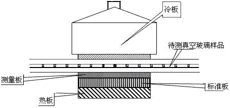
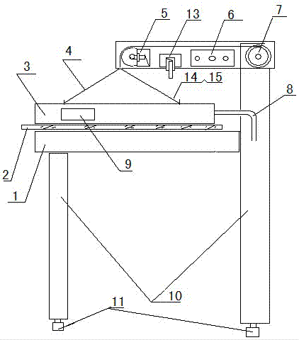
[0030] see image 3 , a vacuum glass thermal conductivity measurement device, including a bracket 10, a horizontal hot plate 1 is arranged on the left side of the bracket 10, a cold plate 3 is arranged above the hot plate 1, and the cold plate 3 communicates with the cooling hose 8, The upper part of the cold plate 3 bypasses the movable pulley on the vertically rising limit switch 5 through three soft ropes and is connected with the electric wheel 7. The displacement of the cold plate 3 in the vertical direction is also limited by the descending limit switch 13 vertically arranged on the crossbeam 12. , The beam 12 is also provided with a control device 6, and the electric wheel 7 is connected with the driving motor. The control device 6 realizes signal processing and issues corresponding instructions as req...


PUM


Abstract

The invention relates to a device for measuring the thermal conductivity of vacuum glass, which comprises a support, a hot plate is arranged on the left side of the support, and a cold plate is arranged above the hot plate. The cold plate is communicated with a cooling water hose, the upper part of the cold plate is connected with an electric wheel by winding around a movable pulley of a vertical lifting limit switch on a cross beam via three soft ropes, the vertical displacement of the cold plate is also limited and coiled by a falling limit switch and a control device, and the hot and cold plates are ensured to stay in horizontal position state. The hot and cold plates can be ensured to stay in horizontal state by adjusting the length of the three soft ropes. Once the hot plate is in contact with the upper surface of the vacuum glass, the three soft ropes are in idle state, so that the pressure drop of the vertical lifting limit switch with the movable pulley almost becomes zero, and a power circuit of a motor is automatically cut off to stop falling. In addition, a level gauge automatically provides a signal about whether the cold plate stays in horizontal state before normal detection. The device has the characteristics of constant pressure in detection, good and uniform contact and accurate detection data.

Description

technical field [0001] The invention relates to a measuring device, which improves the conditions of constant pressure and uniform good contact in actual operation, and in particular relates to a vacuum glass heat conduction measuring device. Background technique [0002] Because the performance of heat insulation and noise reduction of vacuum glass is much better than that of insulating glass, it has a great market prospect in today's theme of energy saving and consumption reduction. The thermal insulation performance parameters of vacuum glass products are represented by their thermal conductivity, which is specifically the sum of radiation thermal conductivity, support thermal conductivity and residual gas thermal conductivity. For qualified vacuum glass products, the residual gas thermal conductivity lead can be ignored. Usually, the measurement of thermal conductivity parameters of vacuum glass is realized by the principle of heat flow method. This is the vacuum glass ...

Claims


Application Information

Patent Timeline
Patent Type & Authority Patents(China)
IPC IPC(8): G01N25/20
Inventor 宁铎金岩张磊辛登科
Owner SHAANXI UNIV OF SCI & TECH
Why Eureka
Try Eureka