
Central laser alignment device for X-ray instrument

A technology of alignment device and X-ray instrument, which is applied in the direction of material analysis using radiation, etc., can solve the problems of difficult adjustment of mechanical positioning mechanism, inability to improve detection efficiency, and inability to reflect products, so as to reduce duplication of labor, easy to observe and Effect of adjustment and cost reduction

Active Publication Date: 2013-11-06
INST OF CHEM MATERIAL CHINA ACADEMY OF ENG PHYSICS
View PDF5 Cites 0 Cited by
  • Summary
  • Abstract
  • Description
  • Claims
  • Application Information

AI Technical Summary

Problems solved by technology

[0004] The general X-ray instrument itself has a mechanical positioning mechanism, but it can only realize the positioning of the outside of the product, and it is powerless for the positioning of the deep hole, slit or cavity inside the product, let alone reflect the deep hole on the product , whether the center of symmetry of the slit or cavity is parallel to the X-ray
In addition, when the geometric center of the X-ray source and the mechanical positioning mechanism do not coincide, the flaw detection position will be deviated, and the mechanical positioning mechanism is difficult to adjust, and this deviation cannot be corrected dynamically
In actual use, it is necessary to correct the position of the product many times and repeat the flaw detection to finally obtain a clear image of the target part, resulting in a waste of imaging negatives and the detection efficiency cannot be improved.

Method used


Image

  • Central laser alignment device for X-ray instrument

Examples


Embodiment Construction

[0024] The present invention will be further described below in conjunction with the accompanying drawings.

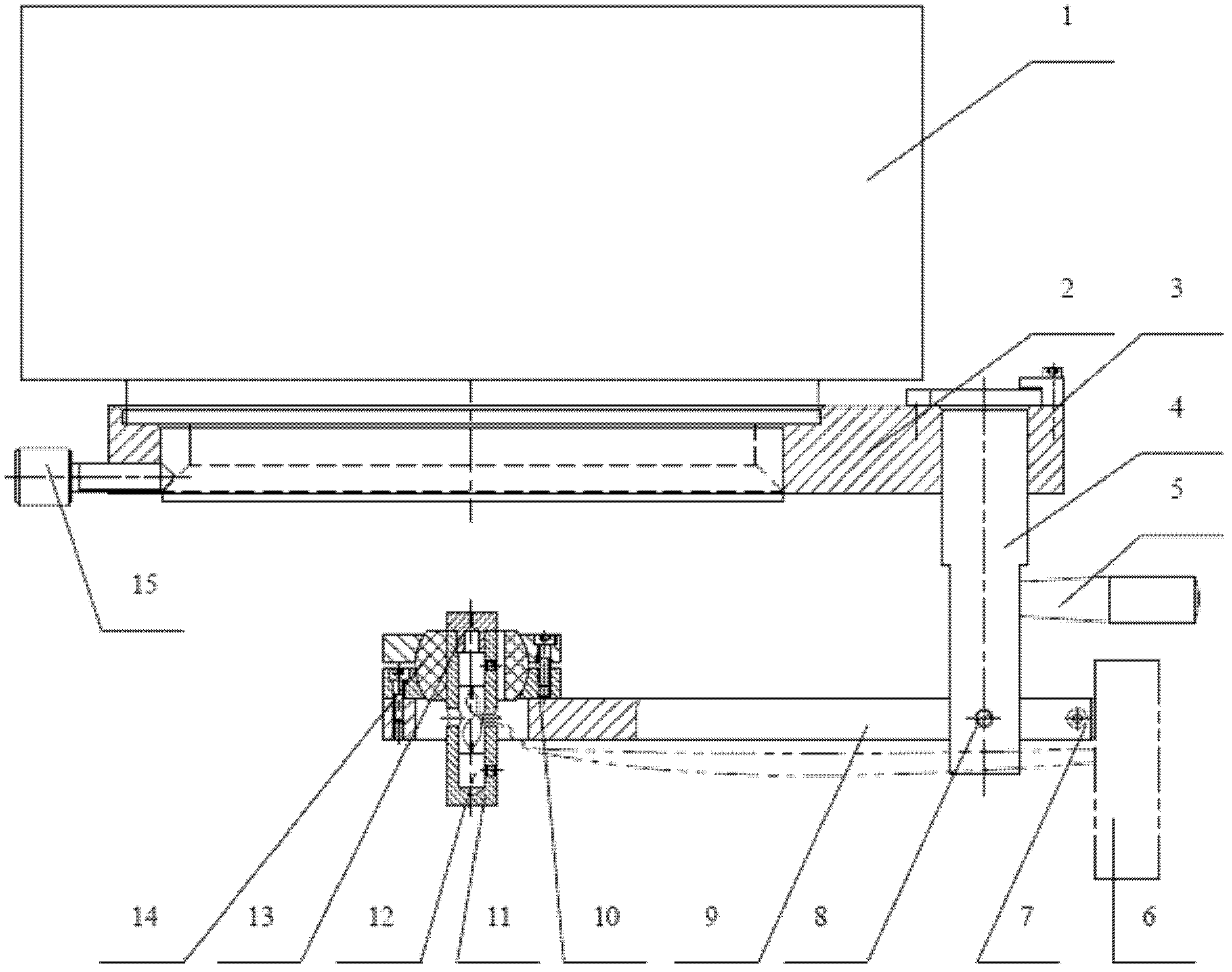
[0025] as attached figure 1 As shown, a laser alignment device for the center of an X-ray instrument includes a connecting plate 2 connected to the X-ray instrument 1, the connecting plate 2 is locked by a locking screw 15, the connecting plate 2 is connected to one end of the rotating shaft 4, and passed through The positioning block 3 fixed on the connecting plate limits the position of the rotating shaft 4. The other end of the rotating shaft 4 is connected to the guide block 9 through a locking screw 8. A handle 5 is installed on the rotating shaft, and a ball seat 10 is fixed on the guide block. The upper is fixedly connected with the adjusting universal ball 14, and the main laser seat 11 is installed on the adjusting universal ball 14 through interference fit. The laser 12 is a visible light laser, and is fixedly installed in the main laser seat 11. The laser s...


PUM


Abstract

The invention discloses a central laser alignment device for an X-ray instrument. The device comprises a connecting plate connected with the X-ray instrument; the connecting plate is locked through a locking screw; the connecting plate is connected with one end of a rotating shaft, the rotating shaft is limited through a positioning block fixed on the connecting plate, and the other end of the rotating shaft is connected with a guiding block; a ball seat is fixed on the guiding block; an adjusting universal ball is arranged on the ball seat; a laser main seat is arranged on the adjusting universal ball in interference fit; and a laser is fixedly arranged in the laser main seat. A laser secondary seat is arranged together with the laser main seat in interference fit. A power supply module is also arranged on the guiding block, and the power supply module is connected with the laser. By using the device, the flaw detection imaging of the X-ray instrument can be clear and accurate, the flaw detection success rate is improved, waste of negative films is reduced, and the cost is reduced. Meanwhile, by adopting the device, repeated labor can be reduced, and the flaw detection efficiency is improved.

Description

technical field [0001] The embodiment of the present invention relates to an X-ray apparatus alignment device, in particular to a center laser alignment apparatus applied to an X-ray apparatus. Background technique [0002] X-ray instrument is a kind of non-contact non-destructive testing equipment, which is used to detect internal defects of products. Its working principle is that the transmitting end emits X-rays, and the X-rays penetrate the detected product and form images on the receiving end film. The transmittance is different, and the shape, size and position of the internal defects of the product can be reflected on the film. [0003] In order to make the image of the detected part of the product clear, the shielding or interference of other parts of the product to X-rays should be minimized, especially for the flaw detection of deep holes, slits or the bottom of the cavity on the product, X-rays are required to be parallel to the deep holes and slits Or the symmet...

Claims


Application Information

Patent Timeline
Patent Type & Authority Patents(China)
IPC IPC(8): G01N23/04
Inventor 樊星戴明鸿赵维李森王建升鲍延年赵仕勇刘金城
Owner INST OF CHEM MATERIAL CHINA ACADEMY OF ENG PHYSICS
Learn More