Eureka AIR delivers breakthrough ideas for toughest innovation challenges, trusted by R&D personnel around the world.

Pressure detection device for hydraulic press

A detection device and hydraulic press technology, which is applied in the direction of fluid pressure measurement by changing ohmic resistance, can solve the problem of high pressure, and can only be used for hydraulic press detection and adjustment in fixed places such as production plants, and cannot meet the requirements of accurate hydraulic press detection and pressure accuracy. Adjustment, bulky cost and other issues, to achieve the effect of meeting precise requirements, facilitating debugging, and reducing pressure loss

Active Publication Date: 2013-11-20
HEBEI POWER TRANSMISSION & TRANSFORMATION +2
View PDF5 Cites 1 Cited by
  • Summary
  • Abstract
  • Description
  • Claims
  • Application Information

AI Technical Summary

Problems solved by technology

The hydraulic pressure detector is mainly composed of a hydraulic cylinder and a pressure gauge. During the detection, the pressure gauge is connected to the hydraulic cylinder to detect the pressure. Due to the limitation of the volume and the working pressure of the hydraulic components, it can only be used as the detection and detection of hydraulic machines below 45 tons. tuning
The pressure test bench can be used to test crimping machines of more than 100 tons, but due to its large size and high cost, it can only be used for the testing and adjustment of hydraulic machines in fixed places such as production plants, and is not suitable for construction where electric power construction is widely distributed and transferred frequently Therefore, it cannot meet the requirements of accurate detection and precise pressure adjustment of hydraulic presses in power construction enterprises

Method used


Image

  • Pressure detection device for hydraulic press
  • Pressure detection device for hydraulic press
  • Pressure detection device for hydraulic press

Examples


Embodiment Construction

[0019] The present invention will be described in further detail below in conjunction with the accompanying drawings and specific embodiments.

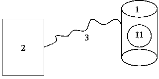
[0020] A hydraulic pressure detection device, such as figure 1 As shown, it includes a voltage changing device 1 , a display controller 2 and a cable 3 , the voltage changing device 1 and the display controller are arranged separately, and the two are connected by a cable 3 . The pressure change device is used to detect the pressure value endured in real time, convert the pressure value into an electrical signal, and transmit it to the display controller. The display controller is used to display the received electrical signal and convert it into a numerical value for display. Of course, the display controller can be calibrated before using the present invention to ensure the accuracy of measurement.

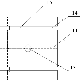
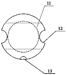
[0021] The voltage change device 1 includes an elastic strain beam, a bridge circuit and connection terminals. The elastic strain be...


PUM


Abstract

The invention relates to a pressure detection device for a hydraulic press. The pressure detection device comprises a pressure change device and a display controller for displaying an adjusted pressure value, wherein the pressure change device and the display controller are arranged in a split way and perform data transmission through a cable; the pressure change device comprises an elastic strain beam and a detection circuit; and a wiring terminal for connecting with the cable is also arranged on the side wall of the elastic strain beam and is connected with the output end of a bridge type circuit. According to the pressure detection device disclosed by the invention, due to the adoption of a split structure, the size of the pressure change device is smaller, and further the requirement on a narrow service environment is met; the display controller can be arranged at any position where debugging can be carried out on according to practical conditions, so that the accurate requirement on pressure detection is met and the requirement on debugging is met; and the precision of pressure detection is further ensured.

Description

technical field [0001] The invention relates to a pressure detection device, in particular to a pressure detection device of a hydraulic machine. Background technique [0002] Hydraulic presses are widely used in electric power construction. However, due to the high working pressure of hydraulic presses and small action positions, there has been no mature solution for accurate detection of pressure and precise adjustment of hydraulic presses. There are usually two types of pressure detectors at present: one is a hydraulic pressure detector, and the other is a pressure test bench. The hydraulic pressure detector is mainly composed of a hydraulic cylinder and a pressure gauge. During the detection, the pressure gauge is connected to the hydraulic cylinder to detect the pressure. Due to the limitation of the volume and the working pressure of the hydraulic components, it can only be used as the detection and detection of hydraulic machines below 45 tons. tuning. The pressure ...

Claims


Application Information

Patent Timeline
Patent Type & Authority Patents(China)
IPC IPC(8): G01L9/04
Inventor 赵国栋刘力强肖中华
Owner HEBEI POWER TRANSMISSION & TRANSFORMATION
Why Eureka
Eureka Blog
Learn More