
Optical fiber ring capable of eliminating influence of external environmental factors

A technology of external factors and fiber optic rings, which is applied in the direction of Sagnac effect gyroscopes, etc., can solve problems such as insufficient influence on the characteristics of fiber optic gyroscopes, changes in the symmetry of fiber optic rings, and affecting the normal operation of fiber optic gyroscopes.

Active Publication Date: 2012-07-18
苏州光环科技有限公司
View PDF3 Cites 12 Cited by
  • Summary
  • Abstract
  • Description
  • Claims
  • Application Information

AI Technical Summary

Problems solved by technology

Because the thermal expansion coefficient of the metal material and the thermal expansion coefficient of the optical fiber are very different, when the external temperature changes, the tension of the optical fiber changes due to the difference in expansion and deformation of the two, which also makes the stress inside the optical fiber Changes occur, which further cause changes in the symmetry of the fiber optic ring, affecting the normal operation of the fiber optic gyroscope
[0009] The current understanding of the error caused by the influence of temperature on the fiber optic gyroscope is still limited. Usually, this error is attributed to the influence of the peripheral circuit system and other components of the fiber optic ring, and no attention is paid to the influence of temperature on the performance of the fiber optic ring. Therefore, It is not enough to fundamentally solve the influence of external temperature changes on the characteristics of fiber optic gyroscopes

Method used


Image

  • Optical fiber ring capable of eliminating influence of external environmental factors
  • Optical fiber ring capable of eliminating influence of external environmental factors
  • Optical fiber ring capable of eliminating influence of external environmental factors

Examples


Embodiment Construction

[0032] The method that the present invention proposes is described as follows in conjunction with accompanying drawing and embodiment:

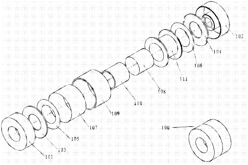
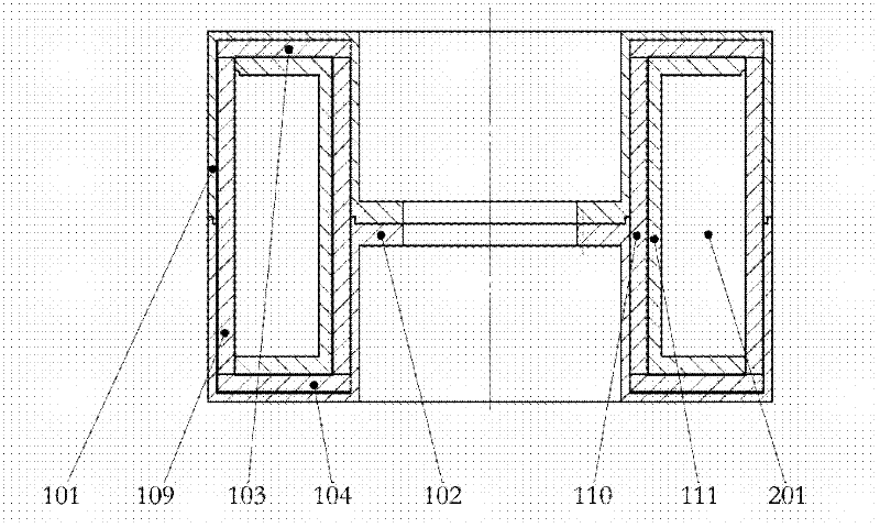
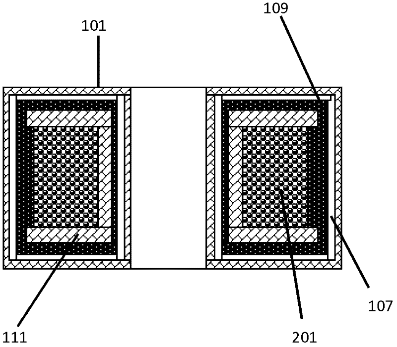
[0033] figure 1It is a schematic diagram of the splitting of an embodiment packaged fiber optic ring (as a fiber optic ring for fiber optic gyroscope), wherein 101 and 102 are a pair of aluminum alloy packaging shells; 111 is a skeleton of a fiber optic ring, and in practical applications, optical fibers are wound on the skeleton; 103, 104, 107, 109, and 110 are thermal insulation material layers, which respectively wrap the entire optical fiber ring at the inner diameter hole, outer circumference, and axial ends of the optical fiber ring. In this embodiment, fiber material insulation cotton with nanometer pores is used as thermal insulation Material layer, this kind of nano-microporous material, due to the existence of nano-micropores, can play a better role in heat insulation; at present, there are some various forms of commercial sales on ...


PUM


Abstract

The invention relates to an optical fiber ring capable of eliminating influence of external environmental factors, and belongs to the technical field of optical measurement and optical fiber sensing. The optical fiber ring comprises a main body formed by winding an optical fiber, and is characterized by further comprising a heat-insulating layer, an optical fiber ring framework and a magnetic shielding material layer, wherein the heat-insulating layer is coated on the surface of the main body and is used for eliminating influence of external factors; the optical fiber ring framework is made of a non-metallic material and is used for being matched with a thermal expansion coefficient of the optical fiber, so that when the outside temperature changes, the accuracy deviation of an optical fiber gyroscope caused by equivalent asymmetry degree due to temperature change of the optical fiber ring can be reduced; and the magnetic shielding material layer is arranged outside the optical fiber ring so as to reduce or eliminate the influence of an external magnetic field on an angle sensor of the optical fiber ring.

Description

technical field [0001] The invention belongs to the technical field of optical fiber sensing; in particular, it relates to adding a heat insulation layer to the optical fiber ring to eliminate the influence of external temperature changes on the symmetry of the optical fiber ring, so as to improve the quality of the optical fiber ring. Background technique [0002] The fiber optic ring is the core component of the fiber optic angle sensor (also known as the fiber optic gyroscope), and its quality directly determines the accuracy of the fiber optic gyroscope. At present, the traditional optical fiber rings are mostly made by wrapping the optical fiber around the metal frame, and then assembling the optical fiber ring into the angle sensor. Angle sensors usually include some active devices, including light sources, modulators, photodetectors, etc.; these devices tend to emit heat during operation, and the heat is often localized, discontinuous and uneven, and the heat will be ...

Claims


Application Information

Patent Timeline
Patent Type & Authority Applications(China)
IPC IPC(8): G01C19/72
Inventor 姚晓天
Owner 苏州光环科技有限公司
Learn More