Elevator shaft wall assembled by combined shaft frames

An elevator shaft and combined technology, applied in the field of elevators, achieves the effects of reducing production costs, shortening the construction period, and improving installation efficiency

Active Publication Date: 2012-07-18
张向阳
View PDF14 Cites 9 Cited by
  • Summary
  • Abstract
  • Description
  • Claims
  • Application Information

AI Technical Summary

Problems solved by technology

[0006] In view of the above-mentioned defects existing in the existing elevator shaft wall, the object of the present invention is to provide an elevator shaft wall assembled with a combined derrick. The hoistway wall assembled with a combined derrick can shorten the construction period, save costs, reduce the cost, and is beneficial to solve the problem of ventilation. The problem of light transmission can improve the installation efficiency and quality of the elevator; the pit construction technology of the present invention has high efficiency and short construction period, which is beneficial to reduce the impact of pit construction on the daily life of residents

Method used


Image

  • Elevator shaft wall assembled by combined shaft frames
  • Elevator shaft wall assembled by combined shaft frames
  • Elevator shaft wall assembled by combined shaft frames

Examples


Embodiment 1

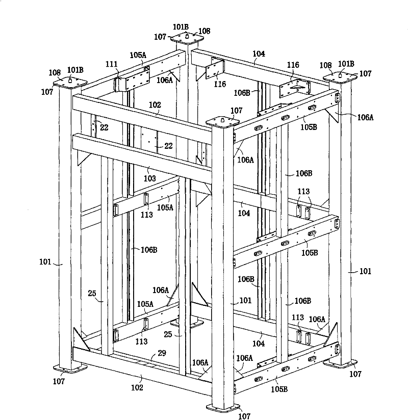
[0055] Embodiment one: if figure 1 , Figure 21 As shown, an elevator shaft wall assembled by a combined derrick includes a steel structure well tower and a pit body 13. The steel structure well tower is composed of more than two derricks 1 according to the number of elevator installation floors. The bottom of the steel structure well tower is horizontally fixed on the anchor bolts 134 on the upper surface of the pit body 13 through high-strength bolts 108A.

[0056] Such as figure 1 As shown, each of the derrick 1 includes four uprights 101, the uprights 101 are distributed at the four corners of the derrick 1, the top and bottom of the uprights 101 are horizontally fixed with a connection seat 107, and the connection seat 107 is provided with 4 connecting holes 108, each of the derricks 1 is connected with high-strength bolts 108A through the connecting holes 108.

[0057] Each said derrick 1 comprises 3 rear beams 104, 3 left side beams 105A and 3 right side beams 105B. ...

Embodiment 2

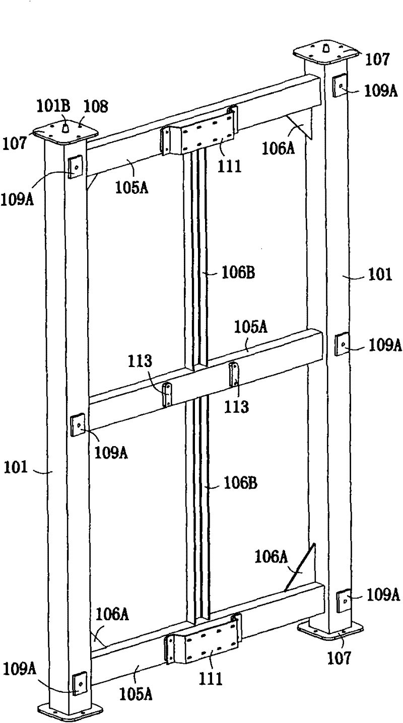
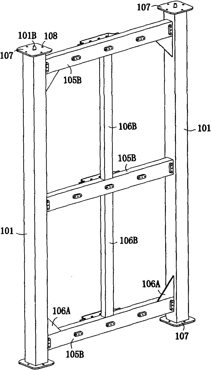
[0079] Embodiment 2: This embodiment is basically the same as the previous example, the difference is that the described derrick adopts the sub-frame processing method. The sub-frame processing method is to decompose the combined derrick 1 into a left frame, a right frame, a front frame and a rear frame, then process them separately, and then assemble it into an integral derrick on the spot.

[0080] figure 2 Left frame right view shown. Described left frame comprises 2 columns 101 on the left side and 3 left side beams 105A, and the two ends of described left side beam 105A are connected laterally with described 2 columns 101 respectively; For increasing intensity, described left A reinforcement plate 106A is provided between the side beam 105A and the column 101, and a reinforcement frame 106B is provided between the left beam 105A; the left frame also includes a car guide rail 110 and three car guide rail frames 111. The car guide rail frame 111 is arranged on the middle...


PUM


Abstract

The invention discloses an elevator shaft wall assembled by combined shaft frames, which relates to lifting equipment. The elevator shaft wall comprises a shaft tower with a metal structure and a bottom pit body, wherein the shaft tower comprises two or more shaft frames, and the bottom of the shaft tower is fixedly mounted on the bottom pit body through high-strength bolts. Each shaft frame comprises four vertical columns and at least eight crossbeams, the vertical columns are distributed at four corners of the shaft frame, the crossbeams are connected with the vertical columns transversely, connecting seats are arranged at two ends of each vertical column and each crossbeam, each connecting seat is provided with at least one connecting hole, and the shaft frames are connected through the connecting holes by the aid of the high-strength bolts. The combined shaft frames can be produced in factories in a standardized manner and can be assembled on site, and by the aid of the elevator shaft wall, construction period can be shortened favorably, cost can be saved, manufacturing cost can be reduced, mounting efficiency and quality of elevators can be improved, and affection on ventilation and lighting for residents during mounting elevators can be reduced. In addition, the elevator shaft wall can be mainly used for old low-rise houses with storeys less than nine.

Description

technical field [0001] The invention and creation title of the prior application of the present invention is "an elevator assembled by a combined derrick", the application number is ZL201120001100.8, and the application date is January 4, 2011. [0002] The present invention relates to a hoisting device, in particular to an elevator. Background technique [0003] The well of the existing elevator is the space provided for the operation of the car and the counterweight, and the space is bounded by the bottom of the well pit, the well wall and the well top. The hoistway is surrounded by hoistway walls, which are used to install elevator components such as car guide rails and counterweight guide rails, and to separate walls or structures between the hoistway and other places. Since most of the old-style low-rise residences did not consider the installation of elevators, it is necessary to build a new well wall when installing an elevator. The new well wall is bounded by the gr...

Claims


Application Information

Patent Timeline
IPC IPC(8): B66B7/00B66B7/02
Inventor 张向阳
Owner 张向阳
Why Eureka
Try Eureka