
Spring pressure-assisted cutting fixing device with double cutting torches and application method of spring pressure-assisted cutting fixing device

A fixing device and spring fixing technology, applied in auxiliary devices, welding/cutting auxiliary equipment, auxiliary welding equipment, etc., can solve the problems of unstable distance between the cutting torch and the steel plate, heavy weight of the slider, and large frictional resistance, etc., to achieve saving The effect of cutting preparation time, light device structure and small frictional resistance

Active Publication Date: 2012-07-18
中石化胜利油建工程有限公司
View PDF8 Cites 5 Cited by
  • Summary
  • Abstract
  • Description
  • Claims
  • Application Information

AI Technical Summary

Problems solved by technology

[0008] The purpose of the present invention is to provide a spring-assisted pressure double cutting torch cutting and fixing device and its use method, which can overcome the defects of the existing device, such as bulky structure, heavy slider weight, large frictional resistance, and unstable distance between the cutting torch and the steel plate

Method used


Image

  • Spring pressure-assisted cutting fixing device with double cutting torches and application method of spring pressure-assisted cutting fixing device
  • Spring pressure-assisted cutting fixing device with double cutting torches and application method of spring pressure-assisted cutting fixing device
  • Spring pressure-assisted cutting fixing device with double cutting torches and application method of spring pressure-assisted cutting fixing device

Examples


Embodiment Construction

[0035] The present invention will be described in further detail below with reference to the accompanying drawings.

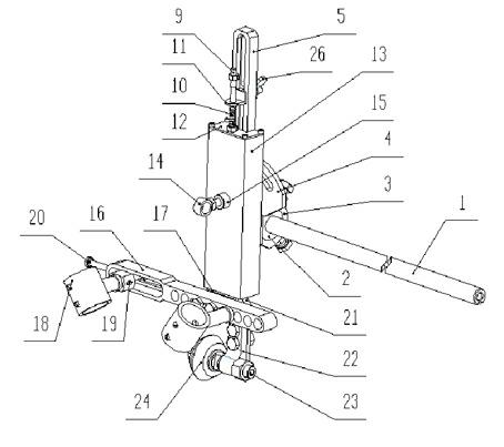
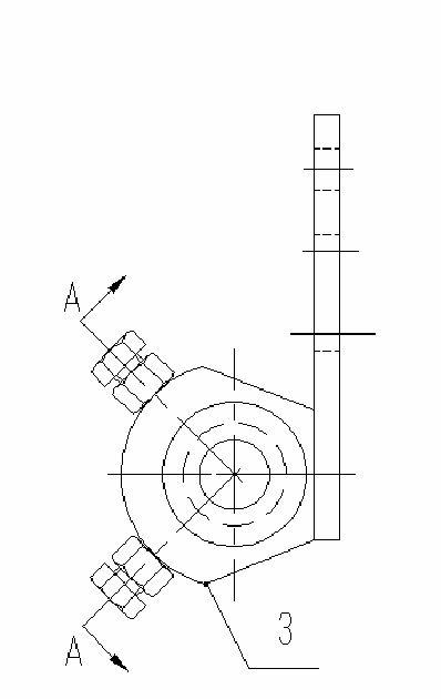
[0036] See figure 1 with figure 2 , The spring-assisted pressure-assisted dual cutting torch cutting fixing device includes a transverse adjustment rod 1, a cutting torch fixing sleeve and a supporting guide wheel 24. The device also includes an arc slit cutting adjustment mechanism, a spring-assisted pressure mechanism, a cutting torch positioning mechanism and a supporting guide wheel. Installation mechanism, the horizontal adjustment rod 1 is connected with the arc slitting adjustment mechanism, the torch fixing sleeve is installed on the torch positioning mechanism, the supporting guide wheel 24 is installed in the supporting guiding wheel installation mechanism; the arc slitting adjustment mechanism is fixed to the spring by bolts On the pressure assisting mechanism, the cutting torch positioning mechanism and the supporting guide wheel installation mechanism...


PUM


Abstract

The invention discloses a spring pressure-assisted cutting fixing device with double cutting torches and an application method of the spring pressure-assisted cutting fixing device, which are quite suitable for cutting grooves of petals of spherical tanks and can simultaneously carry out one-step groove forming cutting for two groove surfaces. The fixing device comprises a transverse adjusting rod, a cutting torch fixing sleeve and a supporting guide wheel, the transverse adjusting rod is connected with an arc seam cutting adjusting mechanism, the cutting torch fixing sleeve is mounted on a cutting torch positioning mechanism, the supporting guide wheel is mounted in a supporting guide wheel mounting mechanism, the arc seam cutting adjusting mechanism is fixed onto a spring pressure assisting mechanism by a bolt, and the cutting torch positioning mechanism and the supporting guide wheel mounting mechanism are mounted on the lower portion of the spring pressure assisting mechanism. The application method includes cutting an upper groove angle beta 1 by the aid of a positioning cutting torch; and cutting a lower groove angle beta 2 by the aid of an adjustable cutting torch in the movable cutting torch fixing sleeve, leading the positioning cutting torch and the adjustable cutting torch to realize cutting simultaneously, and forming an X-shaped cutting line on a spherical shell plate. Owing to spring pressure assistance, the supporting guide wheel always contacts with the steel spherical shell plate along with change of the shape of a cutting plate.

Description

Technical field [0001] The invention relates to an electric welding and cutting fixing device, in particular a spring-assisted pressure type double cutting torch cutting fixing device and a use method thereof, which is very suitable for cutting the grooves of spherical tank petals, and can simultaneously bevel two groove surfaces at one time Forming cutting. Background technique [0002] The steel spherical storage tank is an A3 pressure vessel that stores various gases, liquefied gases and liquids. Compared with other storage vessels of the same volume, it has a small surface area, light weight, uniform force, small footprint, and convenient construction. Advantages such as cost saving. But for the cutting of spherical shell plates, most domestic production units still stay at the technical level of single torch cutting. The biggest disadvantage of single torch cutting technology for cutting the X bevel of the spherical shell plate is the low cutting efficiency. The single to...

Claims


Application Information

Patent Timeline
IPC IPC(8): B23K37/04
Inventor 杨正准迟延国金杰封树森何友谊马达李泮森胡凤英
Owner 中石化胜利油建工程有限公司
Learn More