
Method and implementation device for driving nonmetal flayer with laser

A laser-driven, non-metallic technology, used in laser welding equipment, metal processing equipment, welding equipment, etc., can solve the problem of insufficient space debris ground simulation

Inactive Publication Date: 2012-07-18
TIANJIN UNIV
View PDF4 Cites 20 Cited by
  • Summary
  • Abstract
  • Description
  • Claims
  • Application Information

AI Technical Summary

Problems solved by technology

[0005] However, the current laser-driven flyer technology is limited to driving metal flyers, and its application to the space debris ground simulation is not equivalent to the real space debris environment

Method used


Image

  • Method and implementation device for driving nonmetal flayer with laser
  • Method and implementation device for driving nonmetal flayer with laser
  • Method and implementation device for driving nonmetal flayer with laser

Examples


experiment example 1

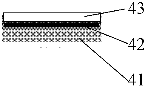
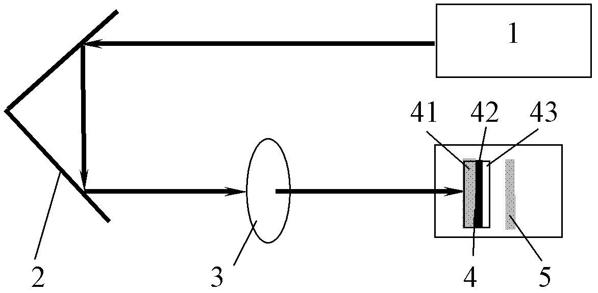
[0028] Preparation of composite flyer target 4:

[0029] First, a silica sol is prepared. Using orthoethyl silicate (TEOS) and γ-(methylpropanoyloxy)propyltrimethoxysilane (MEMO) as precursors, absolute ethanol (EtOH) as solvent, hydrochloric acid (HCl) as catalyst, N , N-dimethylformamide is a film-forming accelerator (DCCA). Mix TEOS, MEMO and EtOH evenly, and after 5 min, add H 2 The mixture of O and HCl is slowly added dropwise, and an appropriate amount of DCCA is added at the same time. The molar ratio of the components in the final solution is TEOS / MEMO / EtOH / H 2 O / HCl is 1 / (0-1.0) / 16 / 6 / 0.03. After the addition, fully stir at room temperature for 40 minutes to obtain a silica sol, seal the obtained sol and naturally age it for 24 hours before coating. Secondly, the quartz glass with a diameter of 40 mm and a thickness of 3 mm was ultrasonically cleaned with deionized water and absolute ethanol for 10 minutes to remove residual organic pollutants on the surface of the...

experiment example 2

[0034] The difference between Experimental Example 2 and Experimental Example 1 is that the laser energy is 300mJ, the trigger frequency is 1Hz, and the laser pulse width is 6ns.

experiment example 3

[0036] The difference between this experimental example 3 and experimental example 1 is that a titanium plate is used as the impact target, the pulsed laser is incident on the quartz glass / carbon layer / silicon dioxide film layer, and the transitional carbon layer on the surface of the quartz glass is ablated and then evaporated instantly. , Gasification and ionization to form plasma, the plasma breaks the silicon dioxide film and is driven by high-speed impact on the titanium plate to form damage. In the experiment, the laser energy is 360mJ, the trigger mode is single trigger, and the laser pulse width is 6ns.


PUM

PropertyMeasurementUnit
reflectanceaaaaaaaaaa

Abstract

The invention discloses a method for driving a nonmetal flyer with laser, which includes the step: enabling the laser generated by a laser device to enter an ablation layer on optical glass, enabling materials on the ablation layer to instantly evaporate, gasify and ionize so that high-temperature and high-pressure plasmas are generated, and under restraint of the optical glass, enabling high-pressure shock waves generated by the plasmas to act on the other face of the ablation layer and be positioned on a nonmetal film in front of an incident area, so that the residual non-metal film is sheared and driven at a high speed, and the high-speed flyer is formed. The method and an implementation device can make up the defect that a current laser-driven flyer can only emit metallic grits so that non-metal grits can be emitted, and can also be applied to the field of high-pressure physics, space science, material micro-forming technology, rapid initiation of explosives and the like. When a space debris environment is simulated in a laser-driven flyer manner in the space science, the debris environment can be efficiently simulated by alternately using various flyer materials.

Description

technical field [0001] The invention relates to the technical field of plasma-driven acceleration, in particular to a method for driving a non-metallic flyer by a laser. Background technique [0002] Since the inception of lasers, extensive research has been carried out on the interaction of lasers with materials. In the early 1990s, humans first proposed the concept of laser drive, that is, using laser to propel objects to fly at high speed. Subsequently, laser-driven flyer technology was gradually discovered. [0003] Laser-driven flyer is a dynamic high-voltage loading technology, and its physical basis is the gasification and ablation of the target caused by strong laser irradiation. In the 1980s, D.L.Paisley achieved the first low-energy laser pulse to drive aluminum and copper, and was the pioneer of laser-driven flyers; in 1990, W.M.Trott broke through the limitations of previous atmospheric transmission and used optical fiber transmission to drive aluminum films; i...

Claims


Application Information

Patent Timeline
Patent Type & Authority Applications(China)
IPC IPC(8): B23K26/18
Inventor 魏强宋丽红高承
Owner TIANJIN UNIV
Learn More