
Improved clamp for connection to the poles of electrical battery

An electrode and battery terminal technology, applied in the direction of connection, conductive connection, electrical component connection, etc., can solve the problems of energy loss, power loss, inability to guarantee clamping force, etc., and achieve the effect of high current density and large contact surface

Inactive Publication Date: 2012-07-11
VIEMME SRL
View PDF6 Cites 8 Cited by
  • Summary
  • Abstract
  • Description
  • Claims
  • Application Information

AI Technical Summary

Problems solved by technology

[0019] As a first disadvantage, this concerns the heating of the connection
[0020] The second disadvantage is that there is energy loss resulting in lower efficiency
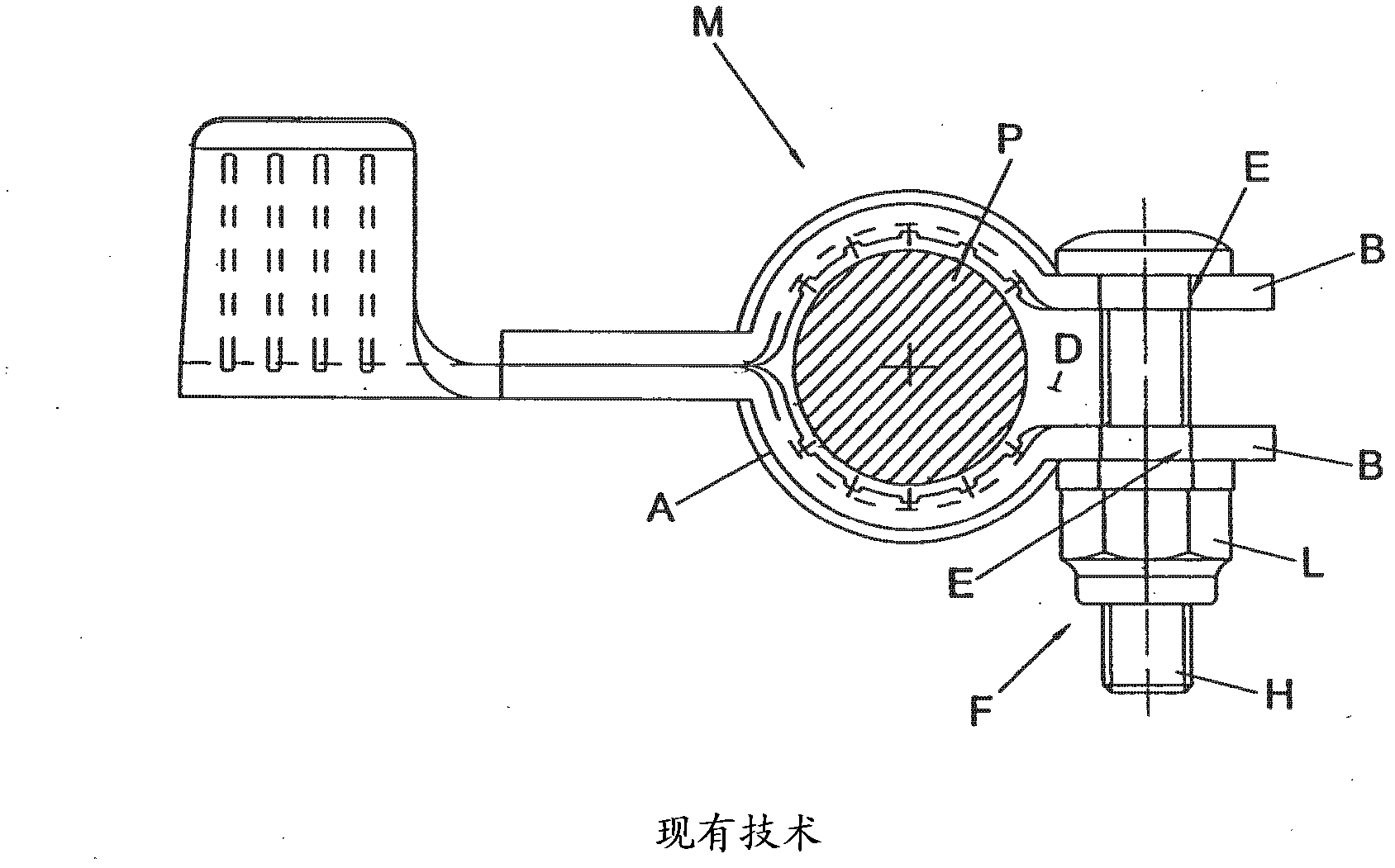
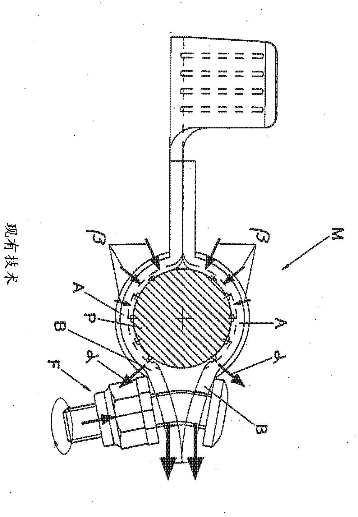
[0022] However, said form of construction causes the disadvantage that the contact between the terminal and the electrode takes place through the deformation of the laminated element of the terminal and the deformation of the shaped part present on the inner edge of the hole in the laminated element accommodating the electrode. After cross penetration in the electrode body
[0027] However, said terminals are provided with interacting surfaces that limit the travel of the fastening means, and therefore, if the diameter of the corresponding electrode is shorter than the standard diameter established for the terminal to which it is coupled, the same clamping force cannot be guaranteed on Corresponding electrode
[0028] In these cases the terminals do not guarantee an optimal connection, especially from an electrical point of view, and this can lead to power loss as well as overheating

Method used


Image

  • Improved clamp for connection to the poles of electrical battery
  • Improved clamp for connection to the poles of electrical battery
  • Improved clamp for connection to the poles of electrical battery

Examples


Embodiment Construction

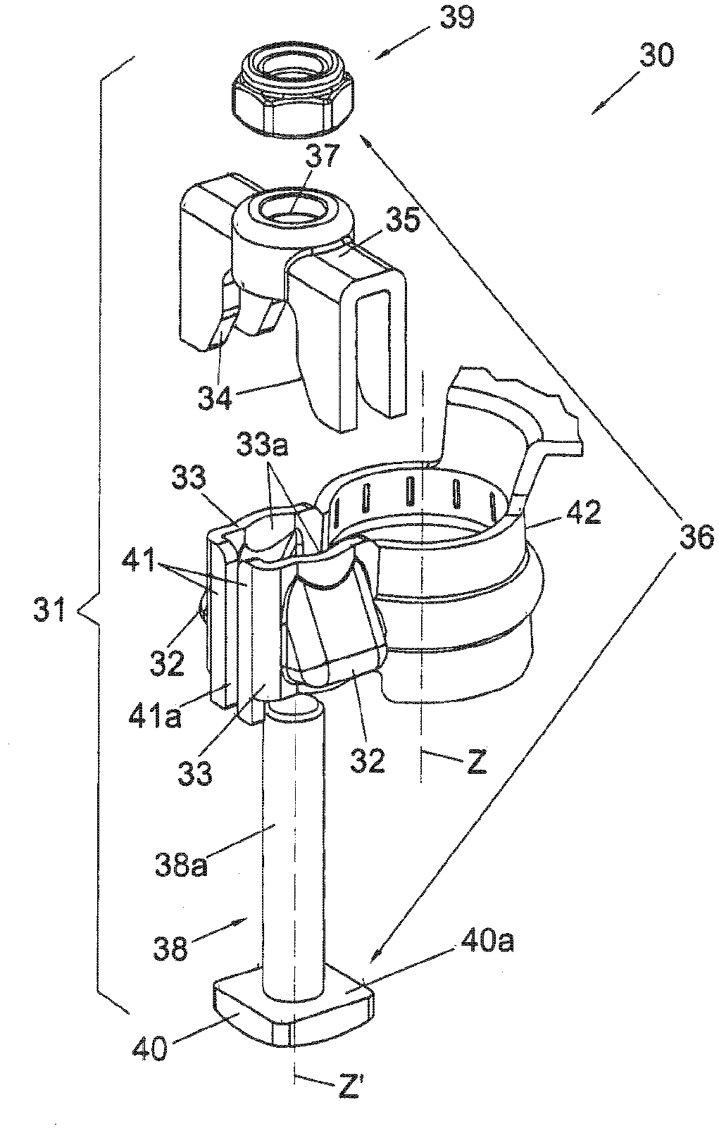
[0054] A first structural variant of the invention is shown in image 3 and Figure 4 In the figure, the terminals, indicated as a whole by 30, are provided with fastening means 31 accessible from above.

[0055] This embodiment is particularly useful when the space around the terminal 30 is restricted and makes it difficult to access the fastening means in a transverse direction with respect to the direction defined by the longitudinal axis Z of the electrode P.

[0056] This occurs, for example, when the battery cover is of the type provided with a protective casing adapted to house the electrode P and the terminal 30 when they are coupled together.

[0057] In these cases, the walls defining the housing prevent lateral access to the fastening means if these are made as described and shown above.

[0058] refer to image 3 , the fastening device 31 includes a pair of inclined planes 32 arranged on the outside of the laminated element 33, a pair of inclined corresponding pla...


PUM


Abstract

IMPROVED CLAMP FOR CONNECTION TO THE POLES OF ELECTRICAL BATTERY

Description

technical field [0001] The present invention relates to an improved terminal for connection to the poles of a stationary battery, for use in starting or pulling applications. Background technique [0002] As is known to those skilled in the art, dedicated removable terminals are used to connect electrical equipment and devices to the power battery. [0003] These terminals are provided with means for fastening to the battery poles and means for connecting to the terminals of the electrical wires that supply the electrical equipment. [0004] An important disadvantage posed by the battery terminals of the known art is that the fastening means are only accessible laterally with respect to the electrodes to which they are applied. [0005] The space around the terminal is generally restricted and makes it difficult to access the fastening means in a transverse direction relative to the direction defined by the longitudinal axis of the electrode. [0006] This occurs, for exam...

Claims


Application Information

Patent Timeline
Patent Type & Authority Applications(China)
IPC IPC(8): H01R11/28
CPCH01R11/283H01R11/286H01R11/28
Inventor 丹尼洛·法科莫雷诺·弗兰科弗朗切斯科·阿图索
Owner VIEMME SRL
Learn More