Bandwidth adjustment method and system
A bandwidth adjustment and bandwidth technology used in the field of communications
- Summary
- Abstract
- Description
- Claims
- Application Information
AI Technical Summary
Problems solved by technology
Method used
Image
Examples
Embodiment 1
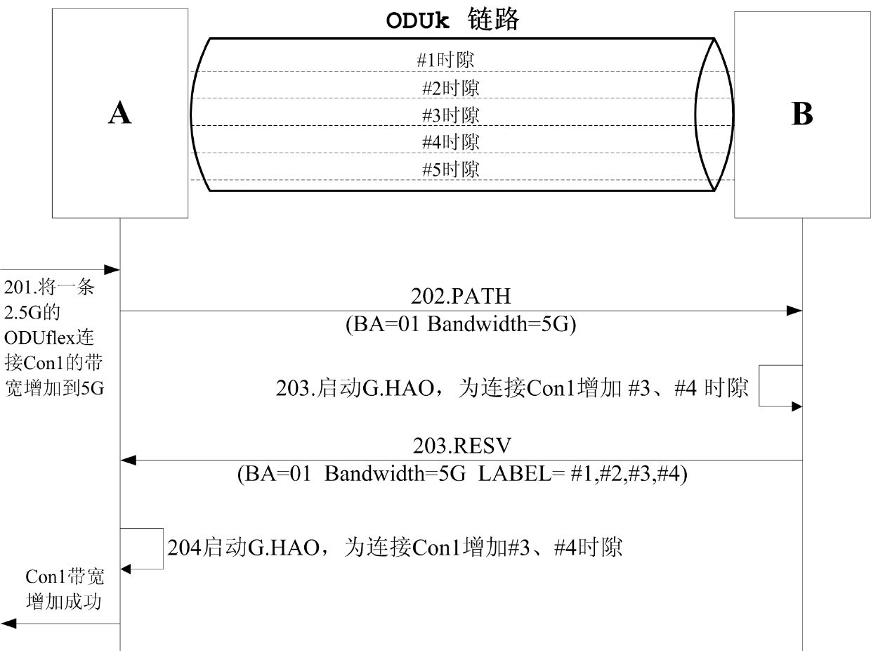
[0071] Combine figure 1 , figure 2 Explain the operation of increasing bandwidth between node A and node B. It is assumed here that an ODUflex unidirectional connection with a bandwidth of 2.5G (denoted as Con1) passes through link AB; and Con1 occupies #1, #2 time slots; #3, #4, and #5 time slots are idle time slots. Now due to business requirements, it is necessary to increase the bandwidth of 2.5G. Here are the steps to implement:
[0072] In step 201, node A receives a request for adding 2.5G bandwidth to the Con1 connection.
[0073] Step 202: The control plane of node A constructs a PATH message in RSVP-TE signaling.
[0074] Here, node A sets the corresponding object according to the following requirements:
[0075] The value of BA in the ADMIN_STATUS object is set to 01;
[0076] The value filled in the service bandwidth field in the Traffic Parameters in the SENDER_TSPEC object is set to 5G;
[0077] Then node A sends the PATH message to node B.
[0078] Step 203: After recei...
Embodiment 2
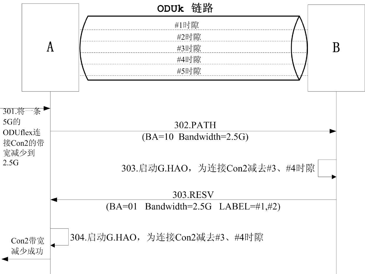
[0084] Combine figure 1 , image 3 Describe the operation of reducing bandwidth between node A and node B. It is assumed here that an ODUflex unidirectional connection with a bandwidth of 5G (denoted as Con2) passes through link AB; and Con2 occupies #1, #2, #3, #4 time slots, and #5 time slot is an idle time slot. Now due to business needs, 2.5G bandwidth needs to be reduced. The following are the implementation steps:
[0085] Step 301: Node A receives a request to reduce 2.5G bandwidth for Con2 connection.
[0086] Step 302: The control plane of node A constructs a PATH message in RSVP-TE signaling. Here, node A needs to set the corresponding object according to the following requirements:
[0087] The value of the BA flag in the ADMIN_STATUS object is set to 10;
[0088] The value filled in the service bandwidth field in Traffic Parameters in the SENDER_TSPEC object is set to 2.5G;
[0089] Then node A sends the PATH message to node B.
[0090] Step 303: After receiving the above...
Embodiment 3
[0095] Combine figure 1 , Figure 4 Explain the operation of increasing bandwidth between node A and node D. It is assumed here that there is an ODUflex bidirectional connection Con1 from A to D with a bandwidth of 2.5G between A, B, C, and D, and Con1 occupies the #1, #2 time slots on the links AB, BC, and CD. Now due to business requirements, it is necessary to increase the bandwidth of 2.5G; and suppose that #8 and #9 timeslots are added on link AB, #5 and #7 timeslots are added on link BC, and # is added on link CD. 3. #4 time slot. The following are the implementation steps:
[0096] In step 401, node A receives a request for adding 2.5G bandwidth to Con1 connection.
[0097] Step 402: The control plane of node A constructs a PATH message in RSVP-TE signaling. Here, node A needs to set the corresponding object according to the following requirements:
[0098] The value of the BA field bit in the ADMIN_STATUS object is set to 01;
[0099] The value filled in the service bandwi...
PUM
 Abstract
Description
Claims
Application Information
 - R&D
- Intellectual Property
- Life Sciences
- Materials
- Tech Scout
- Unparalleled Data Quality
- Higher Quality Content
- 60% Fewer Hallucinations
Browse by: Latest US Patents, China's latest patents, Technical Efficacy Thesaurus, Application Domain, Technology Topic, Popular Technical Reports.
© 2025 PatSnap. All rights reserved.Legal|Privacy policy|Modern Slavery Act Transparency Statement|Sitemap|About US| Contact US: help@patsnap.com


