Electric energy meter
A technology of electric energy meter and voltage channel, which is applied in the field of electric energy meter, can solve the problems of electric energy meter structure complexity and measurement accuracy, and achieve the effect of improving measurement accuracy
- Summary
- Abstract
- Description
- Claims
- Application Information
AI Technical Summary
Problems solved by technology
Method used
Image
Examples
no. 1 example
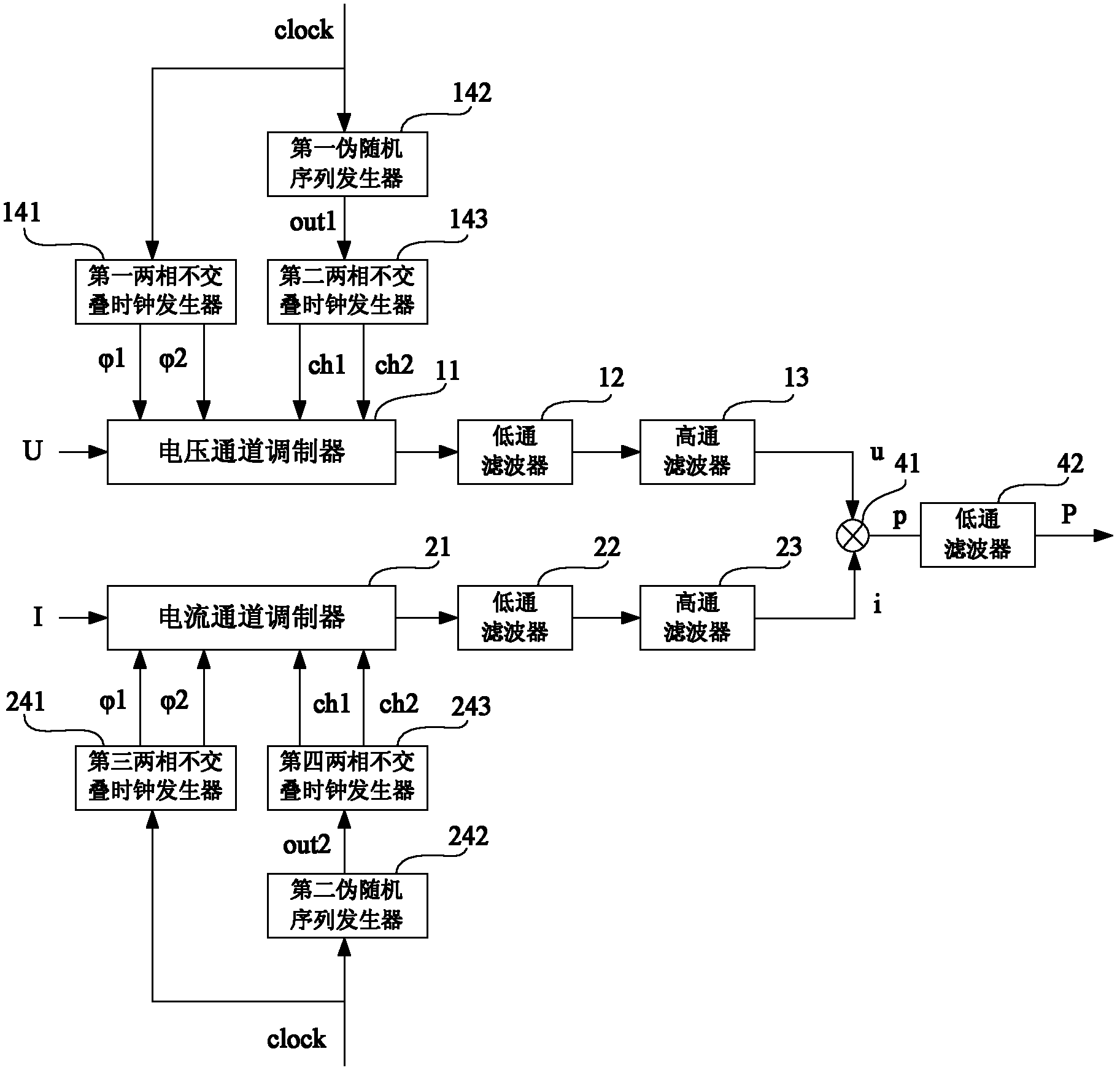
[0042] See figure 2 , shows the circuit structure diagram of the electric energy meter in the first embodiment of the present invention.
[0043] like figure 2 As shown, the electric energy meter includes: a voltage channel analog-to-digital conversion unit, a current channel analog-to-digital conversion unit, and a power calculation circuit. The voltage channel analog-to-digital conversion unit further includes: a voltage channel modulator 11, a low-pass filter 12, a high-pass filter 13, and a first clock generation unit, the first clock generation unit includes a first two-phase non-overlapping A clock generator 141 , a first pseudo-random sequence generator 142 and a second two-phase non-overlapping clock generator 143 . The current channel analog-to-digital conversion unit further includes: a current channel modulator 21, a low-pass filter 22, a high-pass filter 23, and a second clock generation unit, including: the second clock generation unit includes a third two-pha...
no. 2 example
[0066] See Figure 10, shows the circuit structure diagram of the electric energy meter in the second embodiment of the present invention.
[0067] like Figure 10 As shown, the electric energy meter includes: a voltage channel analog-to-digital conversion unit, a current channel analog-to-digital conversion unit, and a power calculation circuit. The voltage channel analog-to-digital conversion unit further includes: a voltage channel modulator 11, a low-pass filter 12, a high-pass filter 13, and a first clock generation unit. The current channel analog-to-digital conversion unit further includes: a current channel modulator 21 , a low-pass filter 22 , a high-pass filter 23 , and a second clock generation unit.
[0068] In the first embodiment, two different pseudo-random sequence generators are provided; in contrast, in the second embodiment, only one pseudo-random sequence generator is provided.
[0069] Specifically, in the second embodiment, the first clock generation u...
no. 3 example
[0072] See Figure 11 , shows the circuit structure diagram of the electric energy meter in the third embodiment of the present invention.
[0073] like Figure 11 As shown, the electric energy meter includes: a voltage channel analog-to-digital conversion unit, a current channel analog-to-digital conversion unit, and a power calculation circuit. The voltage channel analog-to-digital conversion unit further includes: a voltage channel modulator 11, a low-pass filter 12, a high-pass filter 13, and a first clock generation unit. The current channel analog-to-digital conversion unit further includes: a current channel modulator, a low-pass filter 22, a high-pass filter 23, and a second clock generation unit.
[0074] In the first embodiment, two different pseudo-random sequence generators are provided; in contrast, in the third embodiment, only one pseudo-random sequence generator is provided.
[0075] Specifically, in the third embodiment, the first clock generating unit incl...
PUM
 Abstract
Description
Claims
Application Information
 - R&D
- Intellectual Property
- Life Sciences
- Materials
- Tech Scout
- Unparalleled Data Quality
- Higher Quality Content
- 60% Fewer Hallucinations
Browse by: Latest US Patents, China's latest patents, Technical Efficacy Thesaurus, Application Domain, Technology Topic, Popular Technical Reports.
© 2025 PatSnap. All rights reserved.Legal|Privacy policy|Modern Slavery Act Transparency Statement|Sitemap|About US| Contact US: help@patsnap.com


