
Wireless temperature sensor

A wireless temperature and sensor technology, applied in the field of sensors, can solve the problems of inability to obtain the law of continuous change of equipment temperature, inability to realize automatic real-time monitoring, inconvenient installation of measurement points, etc., to achieve accurate and reliable temperature signals, eliminating the need for connection Wire, the effect of unique insulating properties

Inactive Publication Date: 2012-07-11
SHANGHAI MUNICIPAL ELECTRIC POWER CO +3
View PDF6 Cites 6 Cited by
  • Summary
  • Abstract
  • Description
  • Claims
  • Application Information

AI Technical Summary

Problems solved by technology

[0006] 1) Fully automatic real-time monitoring cannot be realized;
[0007] 2) The temperature measurement is inaccurate and easily affected by the environment;
[0008] 3) It is impossible to obtain the law of continuous change of equipment temperature
[0009] The existing temperature sensor adopts an active design and must use a battery, which will have a potential explosion hazard, and it is inconvenient to install the measurement point, and it cannot be replaced with electricity

Method used


Image

  • Wireless temperature sensor
  • Wireless temperature sensor
  • Wireless temperature sensor

Examples


Embodiment Construction

[0029] The present invention will be further described below in conjunction with accompanying drawing.

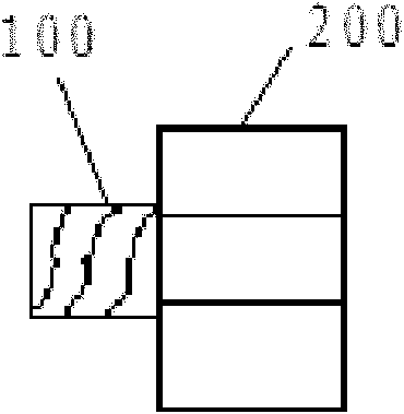
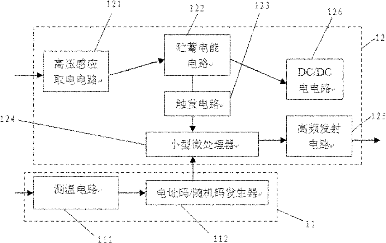
[0030] see figure 1 and figure 2 , a wireless temperature sensor of the present invention is shown in the figure, a wireless temperature sensor 1 is installed on each node that needs to monitor the temperature, and the temperature at the location is automatically measured every set time, and the measured temperature The data is sent and output by wireless signal, and each wireless temperature sensor 1 has an ID number (number) composed of a unique 16bits number, and the installation location of each sensor needs to be allocated and recorded during actual use.

[0031] The appearance of the wireless temperature sensor 1 is in the shape of a bolt, and it includes a threaded screw part 100 and a nut part 200 fixed together. The inside of the nut part 200 is provided with a power-taking processing module 12, and the inside of the screw part 100 is provided with a Temperature...


PUM


Abstract

The invention discloses a wireless temperature sensor in a shape of a bolt. The wireless temperature sensor comprises a screw portion with a thread and a nut portion which are fixed together. An electricity taking and processing module is arranged inside the nut portion, and a temperature sensing module is arranged in the screw portion. The wireless temperature sensor is easy to install and can not have any influence on power equipment. In addition, the wireless temperature sensor only needs to be installed on a tested object at one time, and is used in a long term without replacement, so that the characteristic of passiveness is achieved.

Description

technical field [0001] The invention relates to the field of sensors, in particular to a wireless temperature sensor. Background technique [0002] Monitoring the temperature of power equipment is a very important problem being studied at home and abroad. Measuring the temperature of these contacts and transmitting the data in real time is no easy task. At present, the commonly used measurement methods mainly include the following two types: [0003] (1) Contact temperature labeling method, for example, coating a layer of material that changes color with temperature changes such as temperature-sensitive wax on the surface of bus joints and switch contacts, and roughly determining the temperature range by observing its color change. This method is inaccurate, poorly readable, does not allow for quantitative and real-time measurements, and requires regular staff visits. [0004] (2) Non-contact infrared temperature measurement method, for example, using an infrared measurin...

Claims


Application Information

Patent Timeline
IPC IPC(8): G01K7/00G01K1/02G08C17/02F16B35/00G01K1/024
Inventor 周小凡陈铭陈炜黎德光秦斌
Owner SHANGHAI MUNICIPAL ELECTRIC POWER CO
Learn More