
High-speed rail measurement control point CPIII marking post detector

A measurement control and marker rod technology, which is applied to measurement devices, instruments, etc., can solve problems such as the lack of effective detection methods for assembly accuracy and interchange accuracy.

Inactive Publication Date: 2012-07-11
SOUTHWEST JIAOTONG UNIV
View PDF4 Cites 1 Cited by
  • Summary
  • Abstract
  • Description
  • Claims
  • Application Information

AI Technical Summary

Problems solved by technology

However, there is no effective detection method for the assembly accuracy and interchange accuracy between the rods (that is, between the anchor bolts and the marking pins).

Method used


Image

  • High-speed rail measurement control point CPIII marking post detector
  • High-speed rail measurement control point CPIII marking post detector
  • High-speed rail measurement control point CPIII marking post detector

Examples


Embodiment Construction

[0021] The implementation of the present invention will be further described below in conjunction with the accompanying drawings. However, it should be emphasized that the following embodiments are only exemplary and not intended to limit the scope and application of the present invention.

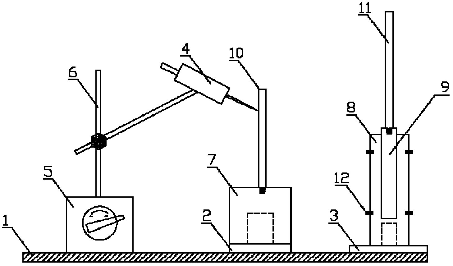
[0022] Figure 1-Figure 8 As shown, the specific implementation method of the present invention is: the base 1 is a long steel plate integral structure, and there are two rotatable cylindrical detection platforms, one high and one short, distributed along the length direction. The bases 2 and 3 of the testing platform are respectively fixed on the base 1, and the two testing platforms are equipped with hollow cylindrical sleeves 7 and 8 which can fit with the bases, and the sleeves can rotate around the outer edge of the base. A threaded opening is left on the top of the cylindrical sleeve 7 of the first testing platform, and the marking pin 10 can be bolted on the testing platform. The ...


PUM


Abstract

The invention discloses a high-speed rail measurement control point CPIII marking post detector, which consists of a base (1), a first cylindrical detection platform and a second cylindrical detection platform which are arranged on the base and are distributed along the length direction of the base, a micrometer dial and a supporting mechanism of the micrometer dial. The base is in a long-strip steel plate integrated structure. The base (2) and the base (3) of the two detection platforms are respectively fixed on the base (1). The two detection platforms are respectively provided with a hollow cylindrical sleeve (7) and a hollow cylindrical sleeve (8) which can be sheathed with the bases and can rotate around the outer edges of the bases. A socket which is used for connecting with a measured marking pin is arranged at the top end of the hollow cylindrical sleeve (7) on the first cylindrical detection platform. A guide hole in which a measured anchoring bolt is inserted is arranged in the hollow cylindrical sleeve (8) on the second cylindrical detection platform. The high-speed rail measurement control point CPIII marking post detector has the advantages that the problem in detecting the machining accuracy of CPIII control point devices is solved and the detector can be effectively used in engineering to improve the repetitive placement and exchange accuracy of CPIII control point marks.

Description

technical field [0001] The invention relates to the track measurement control technology of a high-speed railway passenger dedicated line, in particular to the technical field of three-dimensional control and measurement equipment for a track measurement network (CPIII). Background technique [0002] Before the track construction of the passenger dedicated line, the primary task is to establish the track measurement control network (also known as the foundation pile control network, referred to as the CPIII network, that is, to complete the layout and measurement of the track and turnout pavement control foundation pile points. CPIII control points The spacing is 50-70m, and they are arranged symmetrically on both sides of the line. The installation of CPIII control points generally follows the following principles: [0003] ① When the catenary poles or temporary marking piles are reinforced concrete poles, fix the anchor bolts on the guide holes; [0004] ② When the catena...

Claims


Application Information

Patent Timeline
IPC IPC(8): G01B21/00G01B21/02
Inventor 岑敏仪商立军杨晓云
Owner SOUTHWEST JIAOTONG UNIV
Learn More