Dynamic constant-pressure constant-flow regulating valve
A technology of constant pressure and constant flow, regulating valve, applied in the field of regulating valve, can solve the problems of regulating the faucet, waste, and automatically adjusting the water output of the faucet.
- Summary
- Abstract
- Description
- Claims
- Application Information
AI Technical Summary
Problems solved by technology
Method used
Image
Examples
Embodiment 1
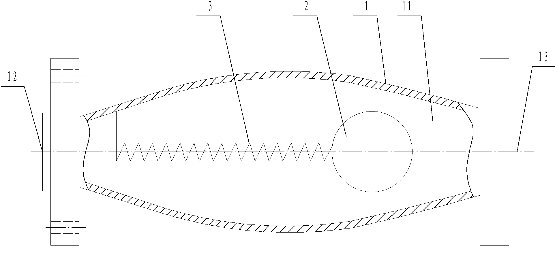
[0028] A dynamic constant pressure and constant flow regulating valve (see figure 1 ), including a valve body 1, a cavity 11 is provided in the valve body 1, and a water inlet 12 and a water outlet 13 are respectively opened at both ends of the valve body 1. The dynamic constant pressure and constant flow regulating valve also includes a throttling ball 2 and Spring 3, one end of the spring 3 is fixed on the valve body 1 near the water inlet 12, the other end is fixedly connected with the throttling ball 2, the throttling ball 2 is located near the water outlet 13, the cross-sectional area of the cavity 11 in the valve body It gradually decreases from the middle to both ends, forming a drum-shaped cavity, but the diameter of the smallest section is larger than the diameter of the throttling sphere 2. When the water pressure is too high and the water flow becomes larger, the throttling sphere 2 is blocked by the water flow. Push toward the water outlet, because the cavi...
Embodiment 2
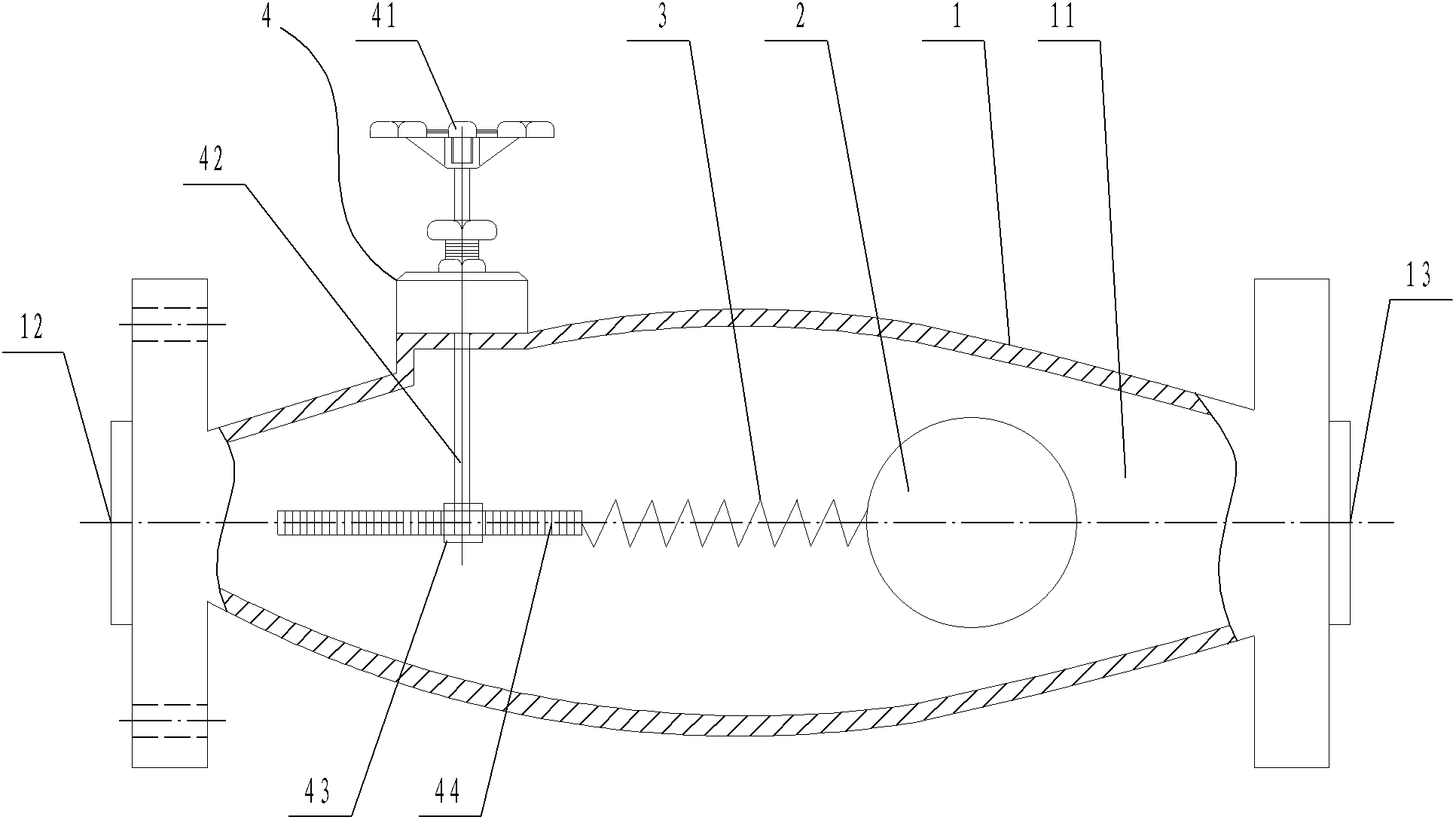
[0030] A dynamic constant pressure and constant flow regulating valve (see figure 2 ), including a valve body 1, a cavity 11 is provided in the valve body 1, and a water inlet 12 and a water outlet 13 are respectively opened at both ends of the valve body 1. The dynamic constant pressure and constant flow regulating valve also includes a throttling ball 2 and Spring 3 and adjusting spring displacement mechanism 4, one end of spring 3 is fixed on the valve body 1 close to the water inlet 12 end, and the other end is fixedly connected with the throttling ball 2, and the cross-sectional area of the cavity 11 in the valve body 1 is determined by the middle It gradually becomes smaller toward both ends to form a drum-shaped cavity, but the diameter at its smallest section is greater than the diameter of the throttle sphere 2; the adjusting spring displacement mechanism 4 includes a hand wheel 41, a valve stem 42, a gear 43, and a tooth Bar 44, wherein the hand wheel 41 is expose...
Embodiment 3
[0031] Embodiment three (best embodiment):
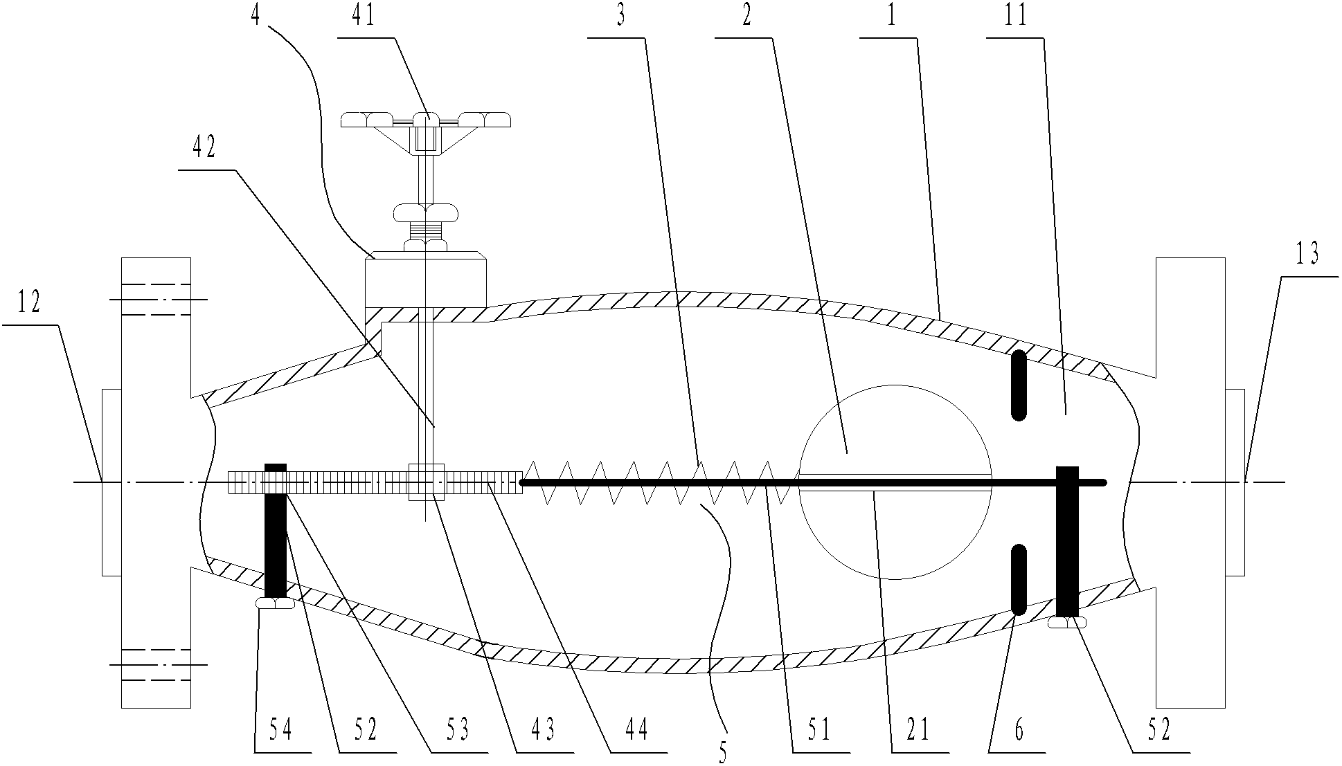
[0032] A dynamic constant pressure and constant flow regulating valve (see image 3 ), including a valve body 1, a cavity 11 is provided in the valve body 1, and a water inlet 12 and a water outlet 13 are respectively opened at both ends of the valve body 1. The dynamic constant pressure and constant flow regulating valve also includes a throttling ball 2 and Spring 3, a through hole 21 is opened in the middle of the throttling sphere 2, one end of the spring 3 is fixed on the valve body 1 close to the water inlet 12, and the other end is fixedly connected with the throttle sphere 2, the inside of the valve body 1 The cross-sectional area of the cavity 11 gradually decreases from the middle to both ends, forming a drum-shaped cavity, but the diameter at the smallest cross-section is greater than the diameter of the throttling sphere 2; the dynamic constant pressure and constant flow regulating valve also includes Adjust the sp...
PUM
 Abstract
Description
Claims
Application Information
 - R&D
- Intellectual Property
- Life Sciences
- Materials
- Tech Scout
- Unparalleled Data Quality
- Higher Quality Content
- 60% Fewer Hallucinations
Browse by: Latest US Patents, China's latest patents, Technical Efficacy Thesaurus, Application Domain, Technology Topic, Popular Technical Reports.
© 2025 PatSnap. All rights reserved.Legal|Privacy policy|Modern Slavery Act Transparency Statement|Sitemap|About US| Contact US: help@patsnap.com


