
Two-stage turbocharging system

A turbocharging system and turbine technology, which is applied to machines/engines, internal combustion piston engines, mechanical equipment, etc., can solve the problem of increasing the flow loss of the exhaust gas of the low-pressure stage turbine wheel, affecting the overall efficiency of the two-stage turbocharging system, and the low-pressure stage turbine. Efficiency reduction and other problems, to achieve the effect of improving the impact, reducing the flow loss of exhaust gas, and improving the utilization rate of exhaust gas energy

Inactive Publication Date: 2012-07-11
TSINGHUA UNIV
View PDF5 Cites 2 Cited by
  • Summary
  • Abstract
  • Description
  • Claims
  • Application Information

AI Technical Summary

Problems solved by technology

[0002] In a conventional two-stage turbocharging system, the exhaust gas swirl at the outlet of the high-pressure stage turbine has a negative impact on the exhaust gas flow inside the low-pressure stage turbine, increasing the loss of exhaust gas flow inside the low-pressure stage turbine wheel, which is due to the low-pressure stage turbine The radial velocity at the blade inlet is low at the blade root and high at the blade tip, resulting in enhanced secondary flow in the turbine of the low-pressure stage turbine, resulting in increased loss of exhaust gas energy, reducing the efficiency of the low-pressure stage turbine and affecting the overall performance of the two-stage turbocharging system efficiency

Method used


Image

  • Two-stage turbocharging system
  • Two-stage turbocharging system
  • Two-stage turbocharging system

Examples


Embodiment Construction

[0021] Embodiments of the present invention are described in detail below, examples of which are shown in the drawings, wherein the same or similar reference numerals designate the same or similar elements or elements having the same or similar functions throughout. The embodiments described below by referring to the figures are exemplary only for explaining the present invention and should not be construed as limiting the present invention.

[0022] In describing the present invention, it should be understood that the terms "center", "longitudinal", "transverse", "upper", "lower", "front", "rear", "left", "right", " The orientations or positional relationships indicated by "vertical", "horizontal", "top", "bottom", "inner", "outer", etc. are based on the orientation or positional relationships shown in the drawings, and are only for the convenience of describing the present invention and simplifying Describes, but does not indicate or imply that the device or element referred...


PUM


Abstract

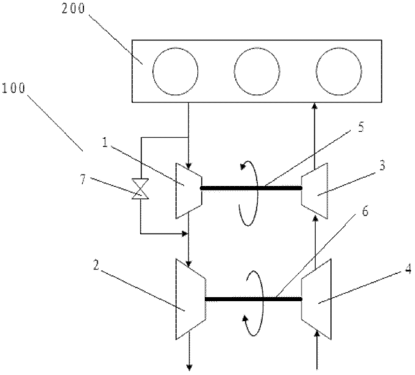
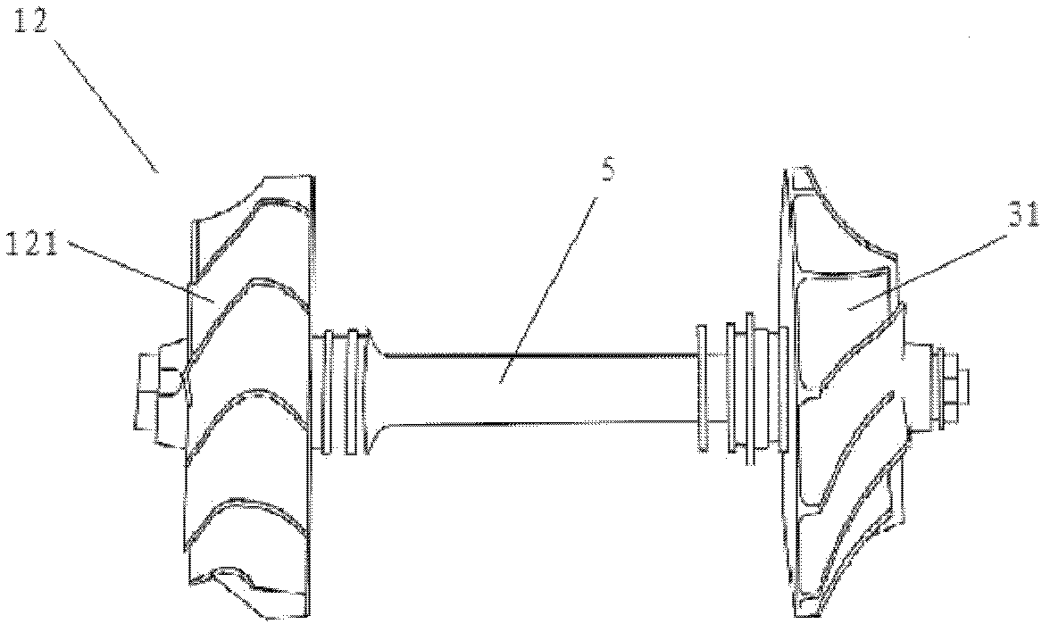
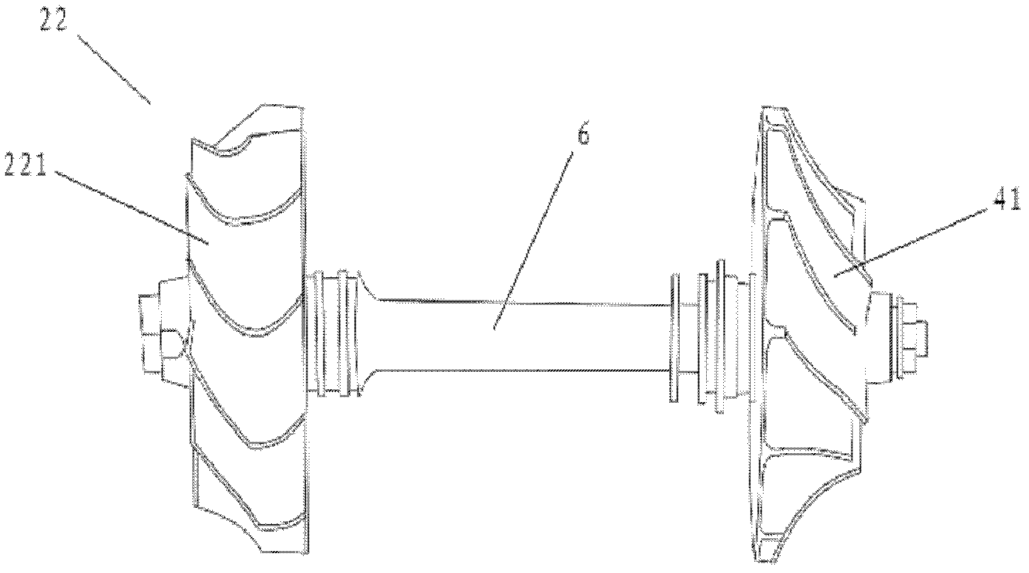
The invention discloses a two-stage turbocharging system, which comprises a high-pressure stage turbomachine, a low-pressure stage turbomachine, a high-pressure stage air compressor and a low-pressure stage air compressor. The high-pressure stage turbomachine comprises a first volute casing and a first turbine, wherein the first turbine is arranged in the first volute casing and provided with a plurality of first blades having first bending directions. The low-pressure stage turbomachine comprises a second volute casing and a second turbine, wherein the second turbine is arranged in the second volute casing and provided with a plurality of second blades in directions opposite to the first bending directions. The high-pressure stage air compressor comprises a first casing and a first impeller, wherein the first impeller is arranged in the first casing and driven by the first turbine. The low-pressure stage air compressor comprises a second casing and a second impeller, wherein the second impeller is arranged in the second casing and driven by the second turbine. In the two-stage turbocharging system, the high-pressure stage turbomachine and the low-pressure stage turbomachine are in counter rotating arrangement, so that the efficiency of the low-pressure stage turbomachine is increased and the integral efficiency of the two-stage turbocharging system is increased obviously.

Description

technical field [0001] The invention relates to the field of supercharging equipment, in particular to a two-stage turbocharging system. Background technique [0002] In a conventional two-stage turbocharging system, the exhaust gas swirl at the outlet of the high-pressure stage turbine has a negative impact on the exhaust gas flow inside the low-pressure stage turbine, increasing the loss of exhaust gas flow inside the low-pressure stage turbine wheel, which is due to the low-pressure stage turbine The radial velocity at the blade inlet is low at the blade root and high at the blade tip, resulting in enhanced secondary flow in the turbine of the low-pressure stage turbine, resulting in increased loss of exhaust gas energy, reducing the efficiency of the low-pressure stage turbine and affecting the overall performance of the two-stage turbocharging system efficiency. Contents of the invention [0003] The present invention aims to solve at least one of the technical probl...

Claims


Application Information

Patent Timeline
Patent Type & Authority Applications(China)
IPC IPC(8): F02B37/013F02B37/18
CPCY02T10/144Y02T10/12
Inventor 诸葛伟林刘艳斌张扬军黄磊张树勇张俊跃胡力峰
Owner TSINGHUA UNIV
Learn More