Variable friction control type oscillating damper of rail wagon

A railway freight car, variable friction technology, applied in the direction of the device for lateral relative movement between the undercarriage and the bogie, can solve the problems of small anti-diamond stiffness, large vibration damping force, unstable vibration damping performance, etc., and achieve improved durability Abrasion resistance, increase the effect of anti-diamond stiffness

Active Publication Date: 2012-07-11
CRRC YANGTZE CO LTD
View PDF9 Cites 12 Cited by
  • Summary
  • Abstract
  • Description
  • Claims
  • Application Information

AI Technical Summary

Problems solved by technology

The constant friction wedge type shock absorber has two main disadvantages: First, in order to take into account the vibration damping performance of empty and heavy vehicles, the vibration damping force is usually too large when the vehicle is empty, and the vibration damping force is too small when the vehicle is heavy. poor performance
[0005] The performance of the railway freight car shock absorber directly affects the dynamic characteristics of the train, and even relates to the safety of the train. Small diamond rigidity and constant friction wedge type shock absorber have the disadvantages of poor vibration damping performance in order to take into account the state of empty and heavy vehicles, but the progress has been slow so far

Method used


Image

  • Variable friction control type oscillating damper of rail wagon
  • Variable friction control type oscillating damper of rail wagon
  • Variable friction control type oscillating damper of rail wagon

Examples


Embodiment Construction

[0014] The present invention will be further described in detail below in conjunction with the accompanying drawings and specific embodiments to facilitate a clear understanding of the present invention, but they do not limit the present invention.

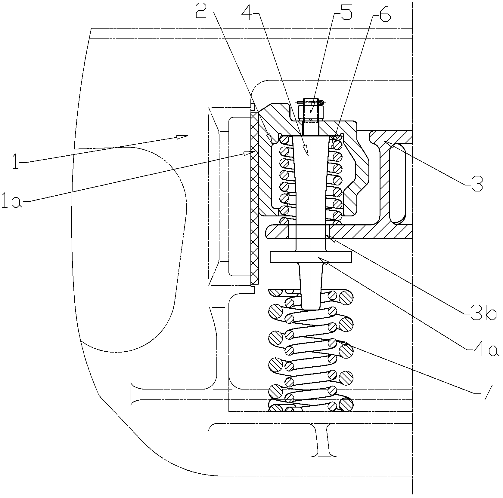
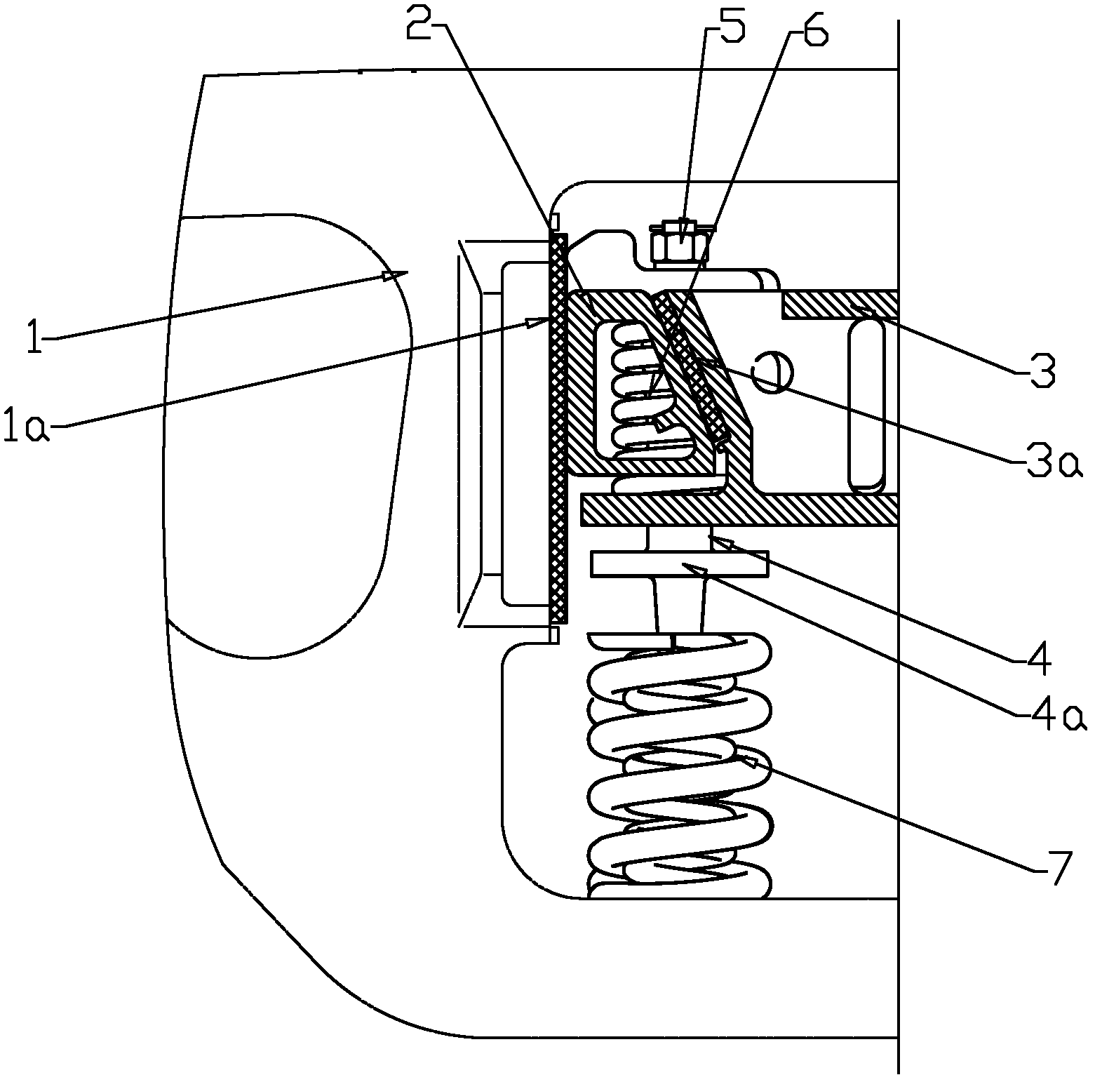
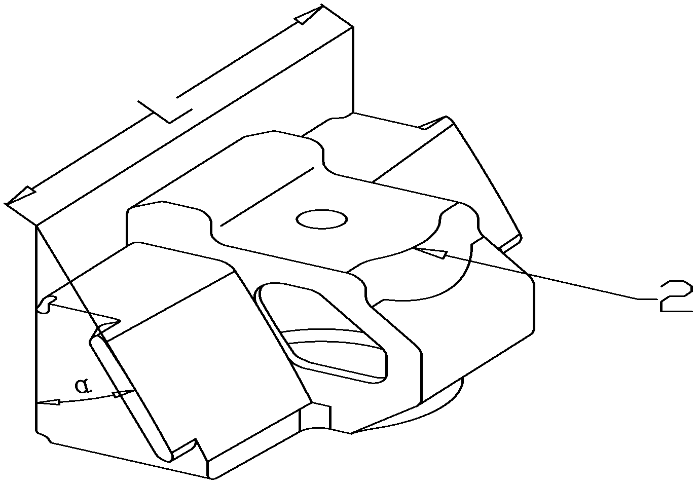
[0015] The variable friction control shock absorber for railway wagons shown in the figure is mainly composed of a wedge body 2 and a damping spring assembly 7 arranged below the wedge body 2 . The lower end of the damping spring assembly 7 is fixed on the central square frame spring bearing platform of the side frame composition 1. The wedge body 2 adopts a structure with a large width and a small apex angle, its main friction surface width L=260mm, and the apex angle α of the wedge body 2=24°. The wedge body 2 is installed in the depression at the end of the bolster component 3, the main friction surface of the wedge body 2 is in contact with the side frame column friction plate 1a of the side frame component 1, and the secondar...


PUM


Abstract

The invention discloses a variable friction control type oscillating damper of a rail wagon. The oscillating damper comprises a tapered wedge body and an oscillation damping spring assembly, wherein the oscillation damping spring assembly is arranged blow the tapered wedge body; the tapered wedge body is installed at the position of an end dent composed of a swing bolster; the lower end of the oscillation damping spring assembly is fixed on a central square frame spring bearing platform formed by lateral frames. The variable friction control type oscillating damper is characterized in that a top rod is arranged in an inner cavity of the tapered wedge body; the upper end of the top rod is connected with the top part of the tapered wedge body through a fastening assembly; the lower end of the top rod passes through a through hole formed by the swing bolster, and a circular boss is arranged at the lower end of the top rod; a tapered wedge inner spring is sleeved on the top rod; the upper end of the tapered wedge inner spring props against the top of the inner cavity of the tapered wedge body; and the lower end of the tapered wedge inner spring props against the platform at the position of the end dent of the swing bolster. Owing to the mechanical property of the tapered wedge inner spring, the circular boss on the top rod is detached from the upper end of the oscillation damping spring assembly in an unloaded state, while propping against the upper end of the oscillation damping spring assembly in a loaded state. The variable friction control type oscillating damper has the characteristics of low abrasion loss, stable oscillation damping performance and large diamond resistant rigidity.

Description

technical field [0001] The invention relates to a damping device on a railway freight car bogie, in particular to a variable friction control type shock absorber for a railway freight car. Background technique [0002] At present, the most commonly used damping elements for railway freight car bogies are friction dampers. Friction dampers are generally composed of wedges and damping springs, and the direction of their force is always opposite to the direction of train movement. function to prevent vibration. The damping resistance of the friction damper directly affects the vibration performance of the train. According to the damping resistance characteristics, it can be divided into two types: variable friction wedge damper and constant friction wedge damper. [0003] The oblique side of the variable friction wedge type shock absorber is inserted into the wedge-shaped groove at the end of the bolster, and the vertical side is pressed against the wear plate of the side fram...

Claims


Application Information

Patent Timeline
Patent Type & Authority Applications(China)
IPC IPC(8): B61F5/12B61F5/06
Inventor 刘爱文徐勇易军恩唐应文肖光毅李永江徐力张良威刘凤伟崔红汤楚强王宝磊姜瑞金严志雄
Owner CRRC YANGTZE CO LTD
Why Eureka
Try Eureka