
Electronic control unit (ECU) mounting structure for automobile

An installation structure and automobile technology, applied in vehicle parts, transportation and packaging, circuits or fluid pipelines, etc., can solve problems affecting the service life of ECU, abnormal noise, etc., to prolong service life, avoid abnormal noise, and reduce accuracy required effect

Active Publication Date: 2012-07-11
CHONGQING CHANGAN AUTOMOBILE CO LTD
View PDF4 Cites 0 Cited by
  • Summary
  • Abstract
  • Description
  • Claims
  • Application Information

AI Technical Summary

Problems solved by technology

In the car, the ECU is fixed and supported by the ECU bracket. The upper and lower ends of the ECU are respectively provided with two mounting lugs with bolt holes. The existing ECU bracket is I-shaped, and its upper and lower ends are respectively provided with two The installation method of the ECU is as follows: the four mounting lugs of the ECU are fixedly connected to the ECU bracket with bolts through the bolt holes and the bolt holes, and the ECU and the ECU bracket are rigidly connected, and there is a large friction And wear, it is easy to cause abnormal noise; at the same time, this installation method has high requirements for the accuracy of the ECU bracket. If the accuracy is not enough, there will be stress between the ECU and the ECU bracket after installation. This abnormal noise and stress will cause Affect the service life of ECU

Method used


Image

  • Electronic control unit (ECU) mounting structure for automobile
  • Electronic control unit (ECU) mounting structure for automobile
  • Electronic control unit (ECU) mounting structure for automobile

Examples


Embodiment Construction

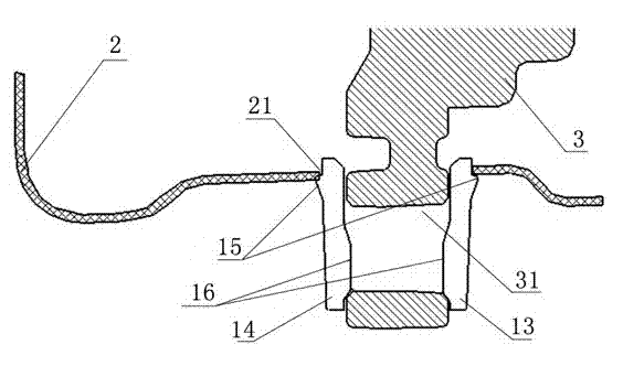
[0014] Such as figure 1 , figure 2 , image 3 The automobile ECU mounting structure shown includes ECU bracket 2 and ECU 3. The upper and lower ends of ECU 3 are respectively provided with two mounting lugs with bolt holes 31. The ECU bracket 2 is L-shaped, and its upper end is provided with two There are two bolt holes, the horizontal part of the lower end is provided with two clamping holes 21, and the ECU sheath 1 is clamped in the clamping holes 21, and the two mounting lugs on the upper end of the ECU 3 pass through the bolt holes 31 and the bolt through holes. It is fixedly connected with the ECU bracket 2 by bolts, and the two mounting lugs at the lower end are snapped into the two ECU sheaths 1 respectively. The ECU sheath 1 is composed of a front splint 13 and a rear splint 14 that are parallel to each other. On the outer side near the upper edge, there is a locking rib 15 parallel to the upper edge. On the inner side, there is a wedge-shaped locking boss 16 whose...


PUM


Abstract

The invention discloses an electronic control unit (ECU) mounting structure for an automobile. The ECU mounting structure comprises an ECU bracket and an ECU, wherein the upper end and the lower end of the ECU are provided with two mounting support lugs with bolt holes respectively; the ECU bracket is L-shaped; the upper end of the ECU bracket has two bolt through holes, and a horizontal part at the lower end of the ECU bracket have two clamping holes; ECU sheaths are clamped in the clamping holes; and the two mounting support lugs at the upper end of the ECU are fixedly connected with the ECU bracket through the bolt holes and bolts for the bolt through holes, and the two mounting support lugs at the lower end of the ECU are clamped in the two ECU sheaths respectively. By the mounting structure, the friction and the abrasion between the ECU and the ECU bracket can be reduced, abnormal noise can be effectively reduced, requirements on the accuracy of the ECU bracket can be reduced, and the service life of the ECU can be prolonged.

Description

technical field [0001] The invention relates to an installation structure of automobile parts, in particular to an installation structure of an automobile ECU. Background technique [0002] The central electronic control unit ECU is an important part of the car, which monitors and controls the various circuit units on the car to perform related functions. In the car, the ECU is fixed and supported by the ECU bracket. The upper and lower ends of the ECU are respectively provided with two mounting lugs with bolt holes. The existing ECU bracket is I-shaped, and its upper and lower ends are respectively provided with two The installation method of the ECU is as follows: the four mounting lugs of the ECU are fixedly connected to the ECU bracket with bolts through the bolt holes and the bolt holes, and the ECU and the ECU bracket are rigidly connected, and there is a large friction And wear, it is easy to cause abnormal noise; at the same time, this installation method has high r...

Claims


Application Information

Patent Timeline
Patent Type & Authority Applications(China)
IPC IPC(8): B60R16/02
Inventor 刘铁男王维兵郑君郭晓强赵书言
Owner CHONGQING CHANGAN AUTOMOBILE CO LTD
Learn More