
Hysteresis massager

A massager and magnetic hysteresis technology, applied in the field of magnetic hysteresis massager, can solve the problems of difficult sealing of the main basin, complex production process and high production cost, and achieve the effects of convenient overall layout, simple production process and low production cost

Inactive Publication Date: 2013-12-04
李林平
View PDF3 Cites 0 Cited by
  • Summary
  • Abstract
  • Description
  • Claims
  • Application Information

AI Technical Summary

Problems solved by technology

[0002] At present, most massagers use mechanical transmission mechanisms such as motors and transmission boxes to realize power transmission for their massage heads. Due to the existence of intermediate transmission components such as transmission boxes, there are many parts, complex structures, and complex production processes. high cost
In addition, the motor as the power source must work in a working environment isolated from water. For example, the motor of the foot massager must be placed outside the main basin, and the rotating shaft of the massage head must pass through the main basin. It is full of water, which brings great difficulties to the sealing of the main basin. If it is not handled properly, it will cause a safety accident due to water leakage.

Method used


Image

  • Hysteresis massager
  • Hysteresis massager
  • Hysteresis massager

Examples


Embodiment Construction

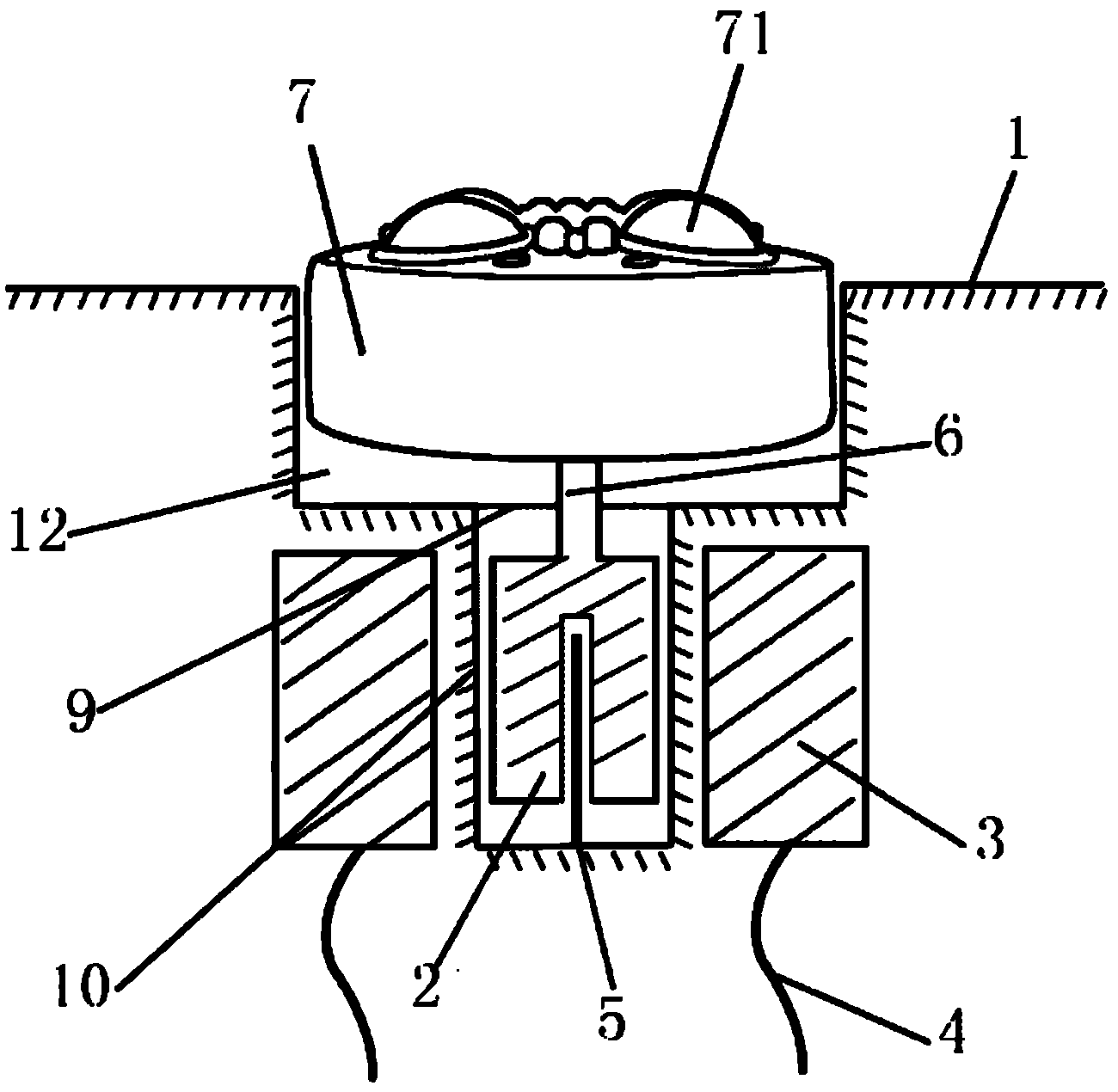
[0026] Such as figure 1 Example 1 is shown. The hysteresis massager includes a main basin body 1, a massage head and a driving mechanism for driving the massage head.

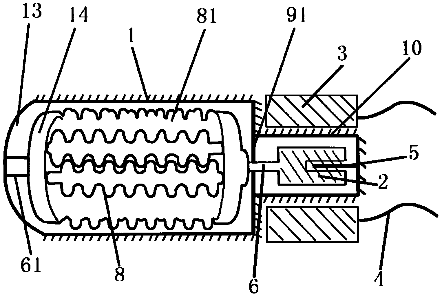
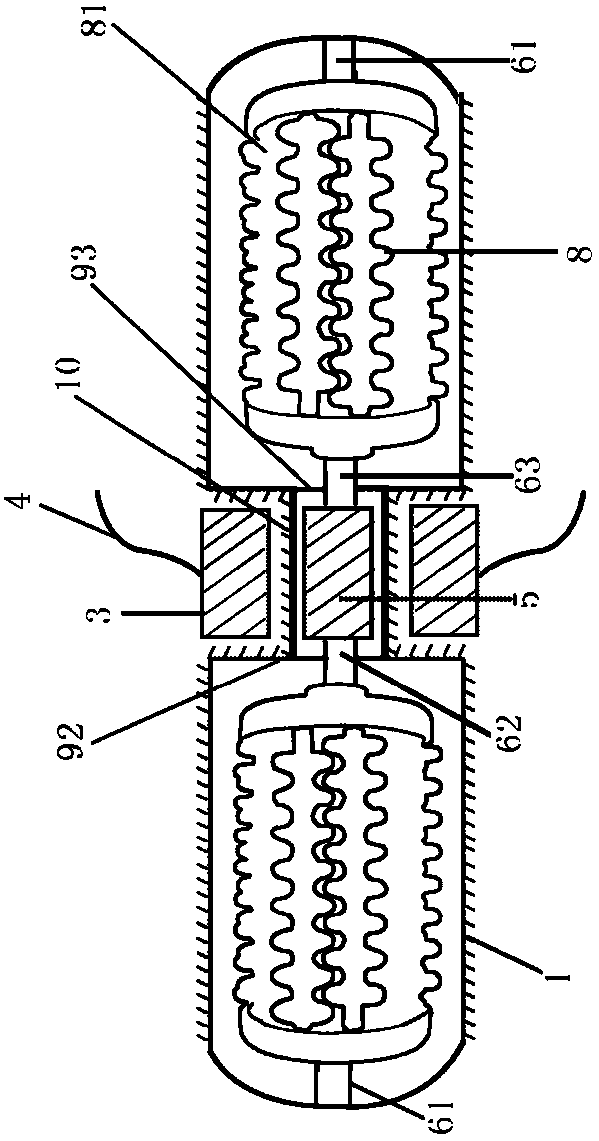
[0027] The drive mechanism includes a magnetic core rotor 2 located in the main basin 1 and a coil 3 located in the interlayer outside the main basin. The main pot body 1 is provided with a rotor chamber 10 for accommodating the magnetic core rotor and cooperating with the magnetic core rotor 2 . The rotor chamber 10 is a columnar chamber. The magnetic core rotor 2 is a cylindrical body containing magnets or magnetizable materials. One end of the magnetic core rotor is axially provided with a rotor center hole, and the axial center positioning shaft 5 fixed on the rotor chamber 10 is placed in the rotor center hole, and the center positioning shaft 5 has a positioning effect on the magnetic core rotor 2, In order to reduce the frictional resistance of the rotor and prevent the partial friction of the magneti...


PUM


Abstract

A hysteresis massager is disclosed, which belongs to physical therapy equipment. The hysteresis massager comprises a main basin body, a massaging head and a drive mechanism, wherein the drive mechanism comprises a magnetic core rotor located in the main basin body and a coil located in the outer interlayer of the main basin body; a rotor chamber for receiving the magnetic core rotor and matched with the magnetic core rotor is disposed on the main basin body; the coil is disposed at the outer side of the rotor chamber or wound on a magnetic conducting material located outside the wall of the rotor chamber and used for conducting a magnetic field, and the rotating magnetic field generated by the coil is applied on the magnetic core rotor; the massaging head is connected with the magnetic core rotor, and a massaging part is disposed on the massaging head; and the coil is led out by a conductive wire and connected to an electric controller. Compared with traditional structure, hysteresis principle is applied to the massager in the hysteresis massager disclosed by the invention; and when the coil is electrified, the coil generates a rotating magnetic field, so that the magnetic core rotor generates hysteresis effect and rotates under the action of the rotating magnetic field to drive the massaging head to work. The hysteresis massager has the advantages of being stable and reliable, low in noise, long in life, low in maintenance cost and the like.

Description

technical field [0001] The invention relates to a health care device, in particular to a hysteresis massager which uses hysteresis phenomenon for health care or physical therapy. Background technique [0002] At present, most massagers use mechanical transmission mechanisms such as motors and transmission boxes to realize power transmission for their massage heads. Due to the existence of intermediate transmission components such as transmission boxes, there are many parts, complex structures, and complex production processes. high cost. In addition, the motor as the power source must work in a working environment isolated from water. For example, the motor of the foot massager must be placed outside the main basin, and the rotating shaft of the massage head must pass through the main basin. It is full of water, which brings great difficulties to the sealing of the main basin, and if it is not handled properly, it will cause a safety accident due to water leakage. Content...

Claims


Application Information

Patent Timeline
Patent Type & Authority Patents(China)
IPC IPC(8): A61H39/04
Inventor 李林平
Owner 李林平
Learn More