
System and method for monitoring liquid oil quality

A quality monitoring and liquid oil technology, applied in the electronic field, can solve the problems of oil pollution, viscosity drop, viscosity rise, etc., to achieve the effect of reducing consumption and pollution, improving service life, and improving life

Active Publication Date: 2012-07-04
BEIJING ANSAIBO TECH
View PDF6 Cites 38 Cited by
  • Summary
  • Abstract
  • Description
  • Claims
  • Application Information

AI Technical Summary

Problems solved by technology

[0003] However, these methods have certain limitations. For example, when inferring the quality of oil and the oil change time by monitoring the running time of the equipment, due to the operation of each equipment (such as engine, transmission, transformer, fried food equipment, etc.) The conditions are different, so the types and quantities of pollutants produced will also be different; and due to the different quantities and types of antioxidants added to various liquid oils (lubricating oil, hydraulic oil, liquid oil, etc.), various liquids The service life of the oil is also different
Therefore, it is unscientific and unreasonable to infer the service life of liquid oil only by using the running time of the equipment
[0004] Another example is the monitoring of the viscosity of liquid oil. When the quality of liquid oil declines, some impurities in the oil will cause the viscosity of the oil to rise, such as the doping of refrigerant liquid; For example, when water and fuel are mixed in lubricating oil; if the above three impurities are mixed into the oil at the same time, it is likely to cause no change in the viscosity of the oil, but the oil is already highly polluted at this time
[0005] To sum up, if only a few parameters in the liquid oil are monitored, there are still cases where problems cannot be detected, and its quality cannot be guaranteed

Method used


Image

  • System and method for monitoring liquid oil quality
  • System and method for monitoring liquid oil quality
  • System and method for monitoring liquid oil quality

Examples


Embodiment Construction

[0044] The principles and features of the present invention are described below in conjunction with the accompanying drawings, and the examples given are only used to explain the present invention, and are not intended to limit the scope of the present invention.

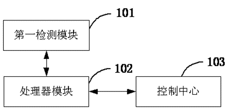
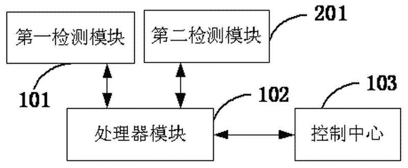
[0045] An embodiment of the present invention provides a liquid oil quality monitoring system, figure 1 It is a logical structural block diagram of the system implementation mode 1 in the embodiment of the present invention, such as figure 1 As shown, the system includes:

[0046] The first detection module 101 is used to detect the liquid oil to obtain various physical and chemical parameters reflecting the quality of the detected liquid oil;

[0047] The processor module 102 is used to compare various physical and chemical parameters of the detected liquid oil obtained by the first detection module 101 with standard values, so as to determine whether the quality of the detected liquid oil meets the standards.

...


PUM


Abstract

The invention relates to a system and a method for monitoring liquid oil quality, which makes scientific and effective judgment on the quality of the liquid oil by simultaneously monitoring multiple physical and chemical parameters of the liquid oil. For instance, when being used for monitoring the qulaity of the lubricating oil of a motor, the system can provide scientific and reasonable advice about when to replace the lubricating oil according to multiple quality standards of the lubricating oil as well as monitoring parameters, thereby being capable of prolonging the service lifetime of a motor, reducing the fuel consumption, and and reducing pollution. Moreover, the system avoids unnecessary replacement, prolongs the service lifetime of the lubricating oil, reduces the quantity of waste oil, and accordingly reduces the pollution thus incurred. The system is also significant in monitoring the quality of transmission oil, transmission liquid oil, and hydraulic oil. Therefore, the system and method for monitoring the liquid oil quality are of significance.

Description

technical field [0001] The invention relates to the field of electronic technology, in particular to a monitoring system and a monitoring method that use sensors to detect the composition and state of liquid oil. Background technique [0002] At present, there are many monitoring methods for the quality of liquid oil substances. These monitoring methods include monitoring the operating time of liquid oil substances at high temperature, monitoring the dielectric constant of liquid oil substances, and monitoring the viscosity of liquid oil substances. Degree monitoring, monitoring of AC impedance of liquid oil substances, etc. [0003] However, these methods have certain limitations. For example, when inferring the quality of oil and the oil change time by monitoring the running time of the equipment, due to the operation of each equipment (such as engine, transmission, transformer, fried food equipment, etc.) The conditions are different, so the types and quantities of pollu...

Claims


Application Information

Patent Timeline
IPC IPC(8): G01D21/02
Inventor 詹姆斯・刘
Owner BEIJING ANSAIBO TECH
Learn More