Device for detecting wave spring optical fiber bending loss
A bending loss and detection device technology, which is applied in the direction of transmitting sensing components with optical devices, can solve the problem of hindering the improvement of the dynamic range and precision of the fiber attenuator, limiting the dynamic range and precision of the fiber attenuator, and the size of the plate cannot be too large and other issues, to achieve reliable and fast testing, low production and operating costs, and high practical value
- Summary
- Abstract
- Description
- Claims
- Application Information
AI Technical Summary
Problems solved by technology
Method used
Image
Examples
Embodiment 1
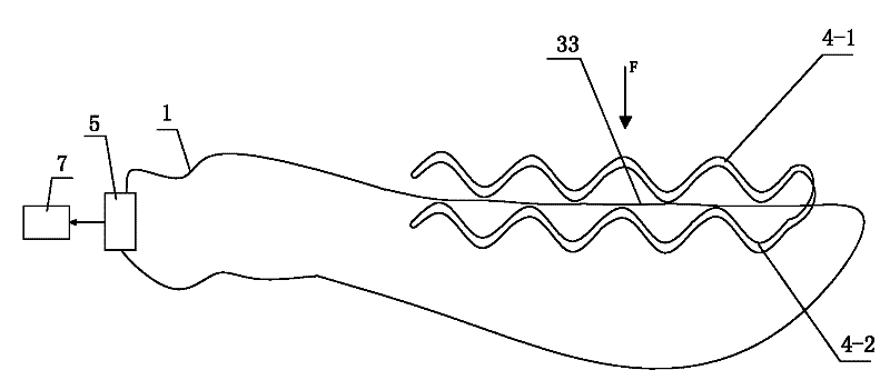
[0043] Such as figure 1 The shown a kind of corrugated spring optical fiber bending loss detection device comprises a first signal optical fiber 33, a curved test channel for the first signal optical fiber 33 to pass through, and is connected to the first signal optical fiber 33 and connected to the first signal optical fiber 33. A test unit 5 for synchronously testing the power variation of the optical signal in the test unit 5, the test unit 5 is connected with a processing unit 7, and the curved test channel includes a curved support 10 composed of at least two layers of corrugated spring wire. The wavy concave-convex of the upper corrugated spring wire-4-1 of the curved support 10 and the wavy concave-convex of the lower corrugated spring wire-4-2 are staggered correspondences, and between the convex heads of the two are formed for one or more first A curved test channel through which the signal optical fiber 33 passes, and the wave-shaped concave-convex of the upper corru...
Embodiment 2
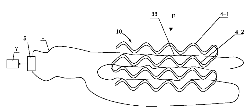
[0047] Such as image 3 As shown, the only difference between this embodiment and Embodiment 1 is that the curved bracket 10 is made of multi-layer corrugated spring wire, which can further extend the length of the first signal optical fiber 33 as the sensing area and improve the test sensitivity. In this embodiment, the structures, connections and working principles of other parts are the same as those in Embodiment 1.
Embodiment 3
[0049] Such as Figure 4 , Figure 5 As shown, the difference between this embodiment and Embodiment 1 is that the curved bracket 10 is formed of a helical structure made of multi-layer corrugated spring wire, which not only prolongs the length of the sensing area of the first signal optical fiber 33, but also improves the test sensitivity. , and other physical quantities can be tested, for example, after the curved stent 10 is bent as a whole, the overall bending curvature can be detected. In this embodiment, the structures, connections and working principles of other parts are the same as those in Embodiment 1.
PUM
 Abstract
Description
Claims
Application Information
 - Generate Ideas
- Intellectual Property
- Life Sciences
- Materials
- Tech Scout
- Unparalleled Data Quality
- Higher Quality Content
- 60% Fewer Hallucinations
Browse by: Latest US Patents, China's latest patents, Technical Efficacy Thesaurus, Application Domain, Technology Topic, Popular Technical Reports.
© 2025 PatSnap. All rights reserved.Legal|Privacy policy|Modern Slavery Act Transparency Statement|Sitemap|About US| Contact US: help@patsnap.com


