
Rotary sintering machine system

A sintering machine system and sintering machine technology are applied in the field of metallurgy, which can solve the problems of low power consumption, good product quality, and low air leakage rate in sinter production, and achieve the effects of improving sinter quality, reducing construction investment, and reducing emissions

Active Publication Date: 2012-07-04
SHANDONG PROVINCE METALLURGICAL ENG CO LTD
View PDF9 Cites 8 Cited by
  • Summary
  • Abstract
  • Description
  • Claims
  • Application Information

AI Technical Summary

Problems solved by technology

[0031] The purpose of the present invention is to overcome the disadvantages of the belt-type sintering equipment in the prior art, such as high air leakage rate of the sintering machine, high power consumption per ton of sintered ore, large investment, low effective utilization rate of trolleys, and high maintenance costs. The sintering equipment has the shortcomings of small equipment specifications, poor product quality, low yield, and low labor productivity. A rotary sintering machine system is provided, so that the rotary sintering machine with low air leakage rate can greatly increase the single machine specification, making sintering Low power consumption in mine production, good product quality and high yield rate, suitable for large and medium-sized sintering plants

Method used


Image

  • Rotary sintering machine system
  • Rotary sintering machine system
  • Rotary sintering machine system

Examples


Embodiment 1

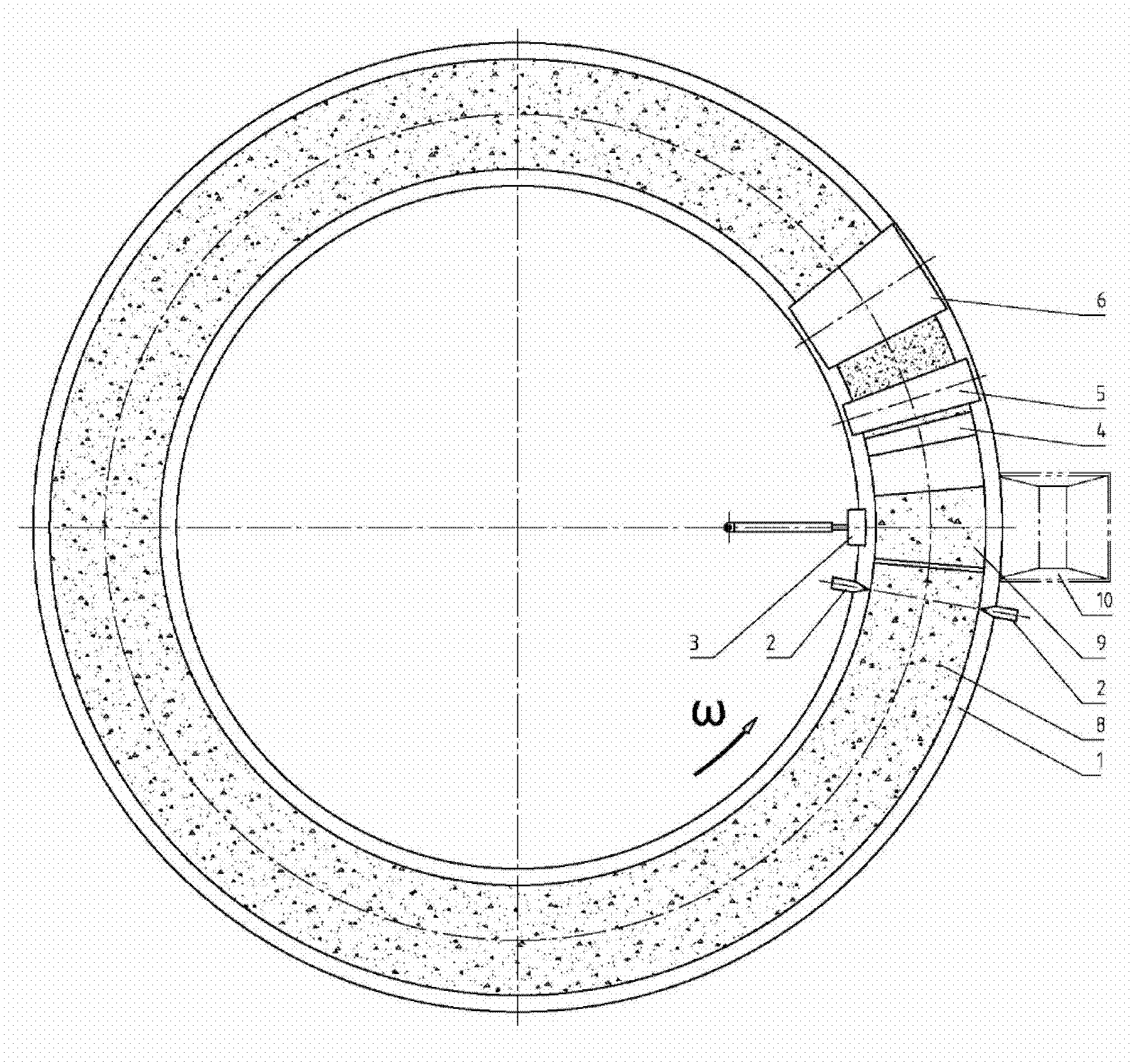
[0068] Embodiment 1 is to realize a kind of rotary sintering machine system of the present invention, in figure 2 Among them, 1 is the rotary sintering machine, 2 is the cutting device, 3 is the unloading device, 4 is the bed material device, 5 is the material distribution device, 6 is the igniter, 8 is the sinter cake, 9 is the short sinter cake, 10 is Crusher feed hopper.

[0069] The effective sintering area of ​​the rotary sintering machine 1 is 300 square meters, the middle diameter is 28 meters, the effective width of the grate bed is 4 meters, the material layer height is 700 mm, the rotation direction is ω, the rotation speed is 1.3 revolutions per hour, and the middle diameter line The speed is 1.92 m / min. The bottom material device 4 is the same as the principle of the prior art, the distribution device 5 is the prior art that adopts the round roller feeder of the prior art to add the multi-roll distributor, and the igniter 6 is the prior art of using gas ignition....

Embodiment 2

[0074] Embodiment 2 is to realize a kind of rotary sintering machine system of the present invention, in figure 2 Among them, 1 is the rotary sintering machine, 2 is the cutting device, 3 is the unloading device, 4 is the bed material device, 5 is the material distribution device, 6 is the igniter, 8 is the sinter cake, 9 is the short sinter cake, 10 is Crusher feed hopper.

[0075] The effective sintering area of ​​the rotary sintering machine 1 is 500 square meters, the middle diameter is 40 meters, the effective width of the grate bed is 5 meters, the material layer height is 800 mm, the rotation direction is ω, the rotation speed is 1.34 revolutions per hour, and the middle diameter line The speed is 2.78 m / min.

[0076] Figure 5 , Figure 6 It is a schematic diagram of the structure of the cutting device 2. The cutting device is a vertical cutting device. The cutting device keeps synchronous movement with the sinter cake during the pressing action, including a frame ...

Embodiment 3

[0080] Embodiment 3 is to realize a kind of rotary sintering machine system of the present invention, in figure 2 Among them, 1 is the rotary sintering machine, 2 is the cutting device, 3 is the unloading device, 4 is the bed material device, 5 is the material distribution device, 6 is the igniter, 8 is the sinter cake, 9 is the short sinter cake, 10 is Crusher feed hopper.

[0081] The total exhaust area of ​​the rotary sintering machine 1 is 125 square meters, wherein the effective sintering area is 62.5 square meters, the cooling area is 62.5 square meters, the middle diameter is 16 meters, the effective width of the grate bed is 3 meters, and the height of the material layer is 800 mm. The direction of rotation is ω, the rotation speed is 1.24 revolutions per hour, and the pitch line speed is 1.01 m / min.

[0082] In this embodiment, 50% of the total ventilation area of ​​the rotary sintering machine is used for cooling the sinter, that is, after the ventilation and sinte...


PUM


Abstract

The invention belongs to the technical field of metallurgy, and relates to a rotary sintering machine system. The system comprises a rotary sintering machine and a discharging device, and a cutting device is arranged at the discharging end of the rotary sintering machine. The cutting device is a horizontal shearing device or a vertical pressure cutting device, and the cutting device moves synchronously with sintered ore cakes during cutting. The discharging device is a driving pushdown discharging device and moves synchronously with the sintered ore cakes during discharging, and a steel wire brush is arranged on the lower part of a pushing head. Through the rotary sintering machine system, the effective area of the single sintering machine can reach 800 square meters, the air leakage rate of the sintering machine is less than 1 percent, and the investment of a supporting dust removal and desulfurization system is reduced by half. When the sintering machine with the scale of 3 million tons of sintered ore per year is constructed by adopting the system, the power consumption can be reduced by 40 million kW.h per year, the power fare of a main exhaust fan is reduced by 20 million yuan per year, the discharge of CO2 is reduced by 41 million tons per year, and the maintenance cost is reduced by 10 million yuan per year, and the discharge of SO2 is reduced by 30 million tons per year.

Description

technical field [0001] The invention belongs to the technical field of metallurgy and relates to a sintering equipment for producing sintered ore. Background technique [0002] Sinter is a man-made lump ore used in ironmaking blast furnaces. From the perspective of global resources, natural lump ore resources that can be directly used in ironmaking blast furnaces are insufficient, and the price has risen. Moreover, directly using a high proportion of natural lump ore will also make the technical and economic indicators of the ironmaking blast furnace worse. The reason is that the smelting performance of natural lump ore is worse than that of sintered ore, which will increase the cost of ironmaking. In order to solve the above-mentioned problems, it is necessary to use a large amount of sintered ore made of iron ore powder as a basic raw material, and to improve the quality of the sintered ore. Therefore, the production of sinter is in an important position that cannot be r...

Claims


Application Information

Patent Timeline
IPC IPC(8): F27B21/08F27B21/12
Inventor 杨东进
Owner SHANDONG PROVINCE METALLURGICAL ENG CO LTD
Learn More