
Lubricant pump and lubricating system with pump heater

A lubricant pump and lubricant technology, applied in the direction of pressure lubrication of lubrication pump, temperature control of lubricant, lubrication pump, etc., can solve the problem of high investment in time and workload

Inactive Publication Date: 2012-07-04
LINCOLN GMBH
View PDF7 Cites 6 Cited by
  • Summary
  • Abstract
  • Description
  • Claims
  • Application Information

AI Technical Summary

Problems solved by technology

This is a high investment of time and effort

Method used


Image

  • Lubricant pump and lubricating system with pump heater
  • Lubricant pump and lubricating system with pump heater

Examples


Embodiment Construction

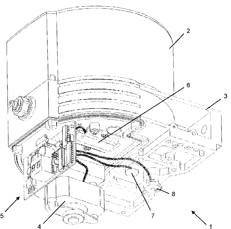
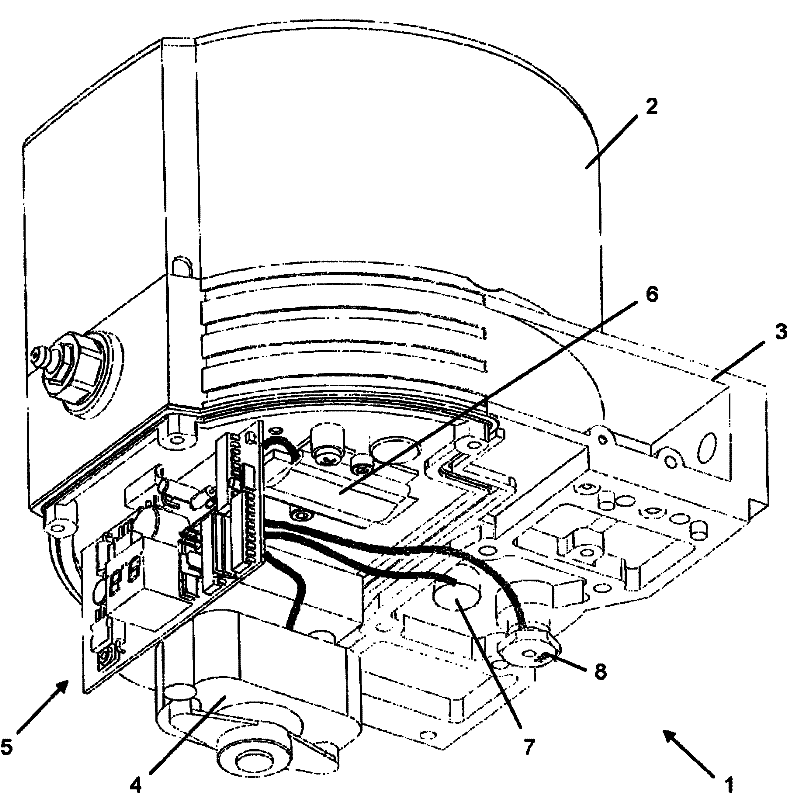
[0017] The lubricant pump 1 according to the invention has a lubricant container 2 in which a lubricant supply is present. A stirring blade or similar stirring device may be provided in the lubricant container 2 in order to stir the lubricant such as grease and keep it flowable. On the lower side in the figure of the lubricant container 2 there is a bracket 3 which can be closed off by a housing cover and on which the components of the lubricant pump 1 are arranged.

[0018] In order to convey the lubricant from the lubricant container 1 to the lubricant outlet, the lubricant pump has a pump unit which can be actuated by the drive motor 4 . The drive motor 4 can also drive the stirring device in the lubricant container 2 .

[0019] In addition, a control device 5 is arranged on the support 3 , which can individually actuate the drive motor 4 or the pump unit and / or the stirring device. In the embodiment shown, a heating element 6 is additionally arranged on the carrier 3 on ...


PUM


Abstract

A lubricant pump is disclosed for delivering lubricant to at least one lubricating point. The pump features a lubricant container (2), a pump unit, a drive (4) assigned to the pump unit, and at least one lubricant outlet and a control unit (5) assigned to the drive (4). At least one heating element (6) is also provided and can be actuated by the control unit and / or another control unit (5). In addition, the invention further relates to a lubricating system with the lubricant pump.

Description

technical field [0001] The invention relates to a lubricant pump for delivering lubricant to at least one lubrication point and to a lubrication system with such a lubricant pump. The lubricant pump has, for example, a lubricant container, a pump unit, a drive assigned to the pump unit, at least one lubricant outlet and a control unit assigned to the drive. Background technique [0002] Some of the known lubricant pumps are provided with a function monitoring system, for example when there is an impermissibly high pressure at the lubricant outlet which indicates a blockage of the line leading to the lubrication point Corresponding fault signals are output to a monitoring device. It is also known that the drive of the pump unit or, if applicable, the drive of the stirring blades arranged in the lubricant container, is automatically switched off and optionally also outputs a fault signal when the load is too high. If such a fault signal is registered in the monitoring device...

Claims


Application Information

Patent Timeline
Patent Type & Authority Applications(China)
IPC IPC(8): F16N13/00
CPCF16N11/08F01M5/001F16N7/14F16N39/04F16N13/00F01M1/02F16N11/00F16N2270/56F16N2250/04F16N2250/08F16N13/22F16N17/00
Inventor Z·帕伦希克A·舍恩菲尔德M·茨韦塔诺维奇
Owner LINCOLN GMBH
Learn More