Automatic clutch device adopting end surface bevel gear engagement

An automatic clutch and meshing technology, applied in magnetic drive clutches, non-mechanical drive clutches, clutches, etc., can solve the problems of difficult separation of gears and low power transmission efficiency.

Inactive Publication Date: 2012-07-04
魏伯卿
View PDF6 Cites 11 Cited by
  • Summary
  • Abstract
  • Description
  • Claims
  • Application Information

AI Technical Summary

Problems solved by technology

[0002] Today's automobile clutches include friction clutches, fluid couplings, and electromagnetic clutches. They all use soft contact, that is, friction, hydraulic force, or electromagnetic force, to transmit the rotational power of the engine. The power transmission efficiency of these soft contacts is relatively high. Low; the reason why the modern developed automobile industry still uses the soft contact clutch method with low power transmission efficiency is because the meshed gears are difficult to separate when the gear meshing transmission rotates at high speed, and no hard transmission that is easy to mesh has not been found yet. The gears are separated, and there is a hard contact meshing transmission method that is even as high as the gear meshing transmission efficiency. This is a difficult problem in improving the transmission efficiency of automobiles.

Method used


Image

  • Automatic clutch device adopting end surface bevel gear engagement
  • Automatic clutch device adopting end surface bevel gear engagement
  • Automatic clutch device adopting end surface bevel gear engagement

Examples


Embodiment Construction

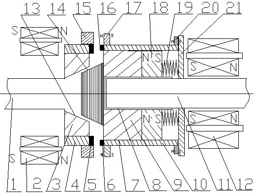
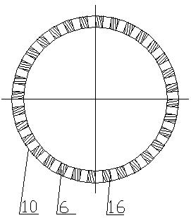
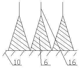
[0018] exist figure 1 In the embodiment shown in —4: the end face bevel gear meshing magnetically controlled automatic clutch device includes a driven shaft wheel 9 sleeved on the driven shaft outer spur gear 8, which can slide back and forth axially with the driven shaft 11 and with the driven shaft 11 Rotate together at the same angular velocity, and the outer ring 10 of the driven shaft wheel is set on the outer spur gear 7 of the driven shaft wheel 9 outside the driven shaft wheel 9 and can slide back and forth along the axial direction and with the driven shaft wheel 9 and the driven shaft 11 rotates at the same angular velocity, and the driven shaft wheel outer ring 10 is close to the driving shaft wheel 3 and has a driven shaft wheel end face bevel gear 6 that matches the driving shaft wheel end face bevel gear 5; the driven shaft wheel 9 is close to the driving shaft wheel 3 one end has the outer friction cone 14 of the driven shaft wheel matched with the inner frictio...


PUM


Abstract

An automatic clutch device adopting end surface bevel gear engagement magnetic control includes a driven shaft wheel sleeved on a driven shaft wheel out spur gear in a magnetic control manner and capable of sliding axially, a driven shaft wheel outer ring sleeved on the sleeved on the driven shaft wheel out spur gear in the magnetic control manner and capable of sliding axially, as well as an endsurface bevel gear at the head part, wherein the end surface bevel gear is engaged with an end surface bevel gear of a driving shaft wheel on a driving shaft wheel outer ring. The automatic clutch device is characterized in that a driven shaft wheel outer friction cone is arranged at one end of the driven shaft wheel, the other end is connected with a driven shaft wheel magnet ring and a driven shaft wheel magnet return spring as well as a driven shaft wheel upper fixing large iron ring sequentially, and a plurality of electromagnetic coils are symmetrically mounted near a driven shaft on theother side of the driven shaft upper fixing iron ring; and a driving shaft wheel inner friction taper hole is arranged at a center zone of one end of the driving shaft wheel, the driving shaft wheel outer ring and the driving shaft wheel end surface bevel gear are arranged on the outer side, and a plurality of electromagnetic coils are symmetrically mounted near a driving shaft outside on the other side of the driving shaft wheel.

Description

technical field [0001] The invention relates to an end-face bevel gear meshing magnetically controlled automatic clutch device, which is suitable for various mechanisms that require clutch speed change and clutch speed regulation, such as clutch speed change devices for various vehicles, gearboxes for lathes, etc., and belongs to the technical field of clutch and gear transmission. Background technique [0002] Today's automobile clutches include friction clutches, fluid couplings, and electromagnetic clutches. They all use soft contact, that is, friction, hydraulic force, or electromagnetic force, to transmit the rotational power of the engine. The power transmission efficiency of these soft contacts is relatively high. Low; the reason why the modern developed automobile industry still uses the soft contact clutch method with low power transmission efficiency is because the meshed gears are difficult to separate when the gear meshing transmission rotates at high speed, and...

Claims


Application Information

Patent Timeline
IPC IPC(8): F16D27/118
Inventor 魏伯卿
Owner 魏伯卿
Why Eureka
Try Eureka