Powerless low-temperature isobaric ammonia recovering method and isobaric ammonia recovering device

An ammonia recovery and ammonia recovery tower technology, applied in separation methods, chemical instruments and methods, ammonia preparation/separation, etc., can solve the problems of large total water volume, large consumption of steam and electricity, low utilization rate of cooling area, etc.

Inactive Publication Date: 2013-07-17
刘军
View PDF5 Cites 0 Cited by
  • Summary
  • Abstract
  • Description
  • Claims
  • Application Information

AI Technical Summary

Problems solved by technology

The process of secondary purification of ammonia, secondary addition of water, and secondary discharge of (dilute) ammonia water is unreasonable, not only consumes more demineralized water, but also discharges dilute ammonia water;
[0018] 3. To absorb ammonia, use soft water or demineralized water, consume power to prepare, transport, and add it to the tower;
[0019] 4. The temperature of soft water or desalted water used to absorb ammonia is also relatively high, which affects the effect of washing ammonia and purifying ammonia, and the ammonia content in tail gas is relatively high;
[0020] 5. The concentration of ammonia water recovered by the isobaric ammonia recovery tower is low, the amount of ammonia water is large, and the total water volume is large. The ammonia water can only go to the urea desorption system and the deep hydrolysis system to distill, concentrate and recycle and use it, which consumes a lot of steam and water. Electricity, these all consume power;
[0021] 6. Unpowered ammonia recovery increases the power consumption of the ammonia compressor in the refrigeration process, and unpowered ammonia recovery actually consumes a lot of power
[0022] 7. Unpowered ammonia recovery and most of the isobaric ammonia recovery towers have high ammonia content in the tail gas outlet. Before the tail gas is dehydrogenated and recovered, the ammonia needs to be cleaned, and steam and electricity are also consumed, as well as power;
[0033] 1. The cooling water tank protruding from the cylinder is a cooling dead angle, and the utilization rate of the cooling area is low;
[0034] 2. Due to the thick tower diameter of the upper cylinder, the relaxation gas and ammonia water in the tower are easy to drift, which affects the effect of absorbing ammonia
[0035] 3. In the relatively low and very limited height between the trays, the cooling area of ​​the coil coolers or small cooling water tanks that can be arranged is small, and the coolers on each tray cannot be distributed from top to bottom. The area is gradually increased;
[0036] 4. The coil cooler or small cooling water tank is used in the upper cylinder, which artificially thickens the cylinder and increases the weight and cost of the equipment;
[0038] 6. The total cooling area of ​​the cooling water tank in the bottom section of the tower is large, but the cooling area on each layer of the upper cylinder is small. The cooling area of ​​the bottom section of the tower and the bottom tray of the adjacent upper cylinder is about 10. The cooling areas of adjacent sections are very different, and the cooling areas of the upper trays are the same, the cooling area distribution of each tray is unreasonable, and the cooling area of ​​some trays is insufficient, which is not conducive to the role of these trays ;
[0039] 7. The poor effect only absorbs ammonia in one stage, and the better effect has eight to eighteen layers of trays. The number of trays is small, and the performance of absorbing ammonia is not high, so the concentration of ammonia water prepared is low, and the ammonia content in the tail gas is high;
[0041] 9. Prepare 45% (weight) high-concentration ammonia water, and reduce the ammonia content of the outlet tail gas to below 0.002% (volume). If all the tray structures are used to absorb ammonia, the height of the cylinder will be very high, the equipment will be very heavy, and the cost will be reduced. will be higher, which is unreasonable and uneconomical

Method used


Image

  • Powerless low-temperature isobaric ammonia recovering method and isobaric ammonia recovering device
  • Powerless low-temperature isobaric ammonia recovering method and isobaric ammonia recovering device
  • Powerless low-temperature isobaric ammonia recovering method and isobaric ammonia recovering device

Examples


Embodiment Construction

[0122] Unpowered low temperature isobaric ammonia recovery method:

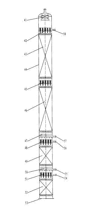
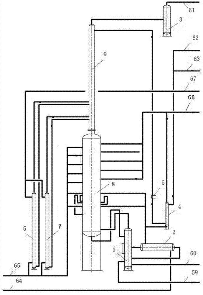
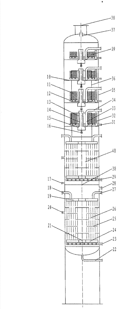
[0123] see figure 1 , the isobaric ammonia recovery tower is composed of two parts, the bubbling absorber 8 at the bottom and the newly added packing scrubber 9 at the top, which are connected by flanges for the convenience of transportation; before the relaxation gas inlet 23 of the bubbling absorber 8 A circulating absorption separator 1 is added, and the outlet and inlet of the high-concentration ammonia water of the circulating absorption separator 1 are connected with the inlet and outlet of the newly added high-concentration ammonia water cooler 2 outside the tower to form a circulation loop for absorbing and cooling the high-concentration ammonia water; The gas outlet of the packing scrubber 9 is connected to the water separator 3, the water inlet is connected to the desalted water pump 5, and a desalted water cooler 4 is added at the inlet or outlet of the desalted water pump 5; A small ammonia water...


PUM

PropertyMeasurementUnit
heightaaaaaaaaaa

Abstract

The invention relates to an ammonia recovering process and ammonia recovering equipment, namely a method and a device for recovering ammonia from gas from ammonia production plants at a low temperature and isobaric pressure. Several or all coolers of the isobaric ammonia recovering device cool ammonia water and absorb water used by ammonia by using liquid ammonia of which the temperature is lower than that of cooling water. The coolers include a double-travel internal cooler in a bubbling absorber, a coil tube type cooler, an out-tower ammonia water cooler, a demineralized water cooler, a first out-tower small ammonia water cooler, a second out-tower small ammonia water cooler. In the invention, ammonia water is cooled without using cooling water, and power is saved; the cooling area of the out-tower ammonia water coolers and the cooling area of the coolers on all layers of tower plates increase gradually from top down and are allocated according to different ammonia absorbing capacities and different dissolution heat released on all layers of tower plates and the cooler loads on the coolers on the layers of tower plates; and thus, the required cooling area is guaranteed and does not wasted, and the ammonia absorbing capacities on all layers of tower plates are fully played.

Description

technical field [0001] The invention relates to an ammonia recovery process and equipment, that is, a method for recovering ammonia under low temperature and isobaric pressure and an isobaric ammonia recovery device in a synthetic ammonia plant. Background technique [0002] In the prior art, in terms of the process technology of isobaric ammonia recovery, various coolers inside and outside the tower of various isobaric ammonia recovery towers use normal temperature circulating cooling water or deep well water with lower temperature Cooling ammonia water, cooling water, circulation and transportation of circulating cooling water will consume power, and extraction and transportation of deep well water will also consume power. To absorb ammonia, soft water or demineralized water is used. The preparation of soft water or demineralized water requires power consumption, and pumping soft water or demineralized water to the top of the constant pressure ammonia recovery tower also c...

Claims


Application Information

Patent Timeline
Patent Type & Authority Patents(China)
IPC IPC(8): B01D53/18C01C1/12
Inventor 刘军
Owner 刘军
Why Eureka
Try Eureka