
Cup fetching machine

A technology of a cup fetching machine and a robotic arm, which is applied to conveyor objects, transportation and packaging, etc., can solve the problems of waste of resources, low efficiency of the cup fetching machine, and the speed of the glass cup pressing machine cannot be improved. Effect

Inactive Publication Date: 2012-07-04
刘亢
View PDF8 Cites 10 Cited by
  • Summary
  • Abstract
  • Description
  • Claims
  • Application Information

AI Technical Summary

Problems solved by technology

[0002] At present, the cup taking machine used in the glass industry is a one-hand swinging cup taking machine, and there must be a useless work in the round-trip process of the one-handed swinging cup taking machine. Due to the low efficiency of the supporting cup taking machine, it eventually leads to The speed of the glass press upstream of the cup remover cannot be increased
Simultaneously, because the position of placing the cup after taking the cup is fixed in the existing cup machine, it cannot be matched with the double-station glass mouth dryer located downstream of the cup machine, resulting in the inability of the double-station glass mouth dryer. play a role, resulting in waste of resources and low production efficiency

Method used


Image

  • Cup fetching machine
  • Cup fetching machine
  • Cup fetching machine

Examples


Embodiment Construction

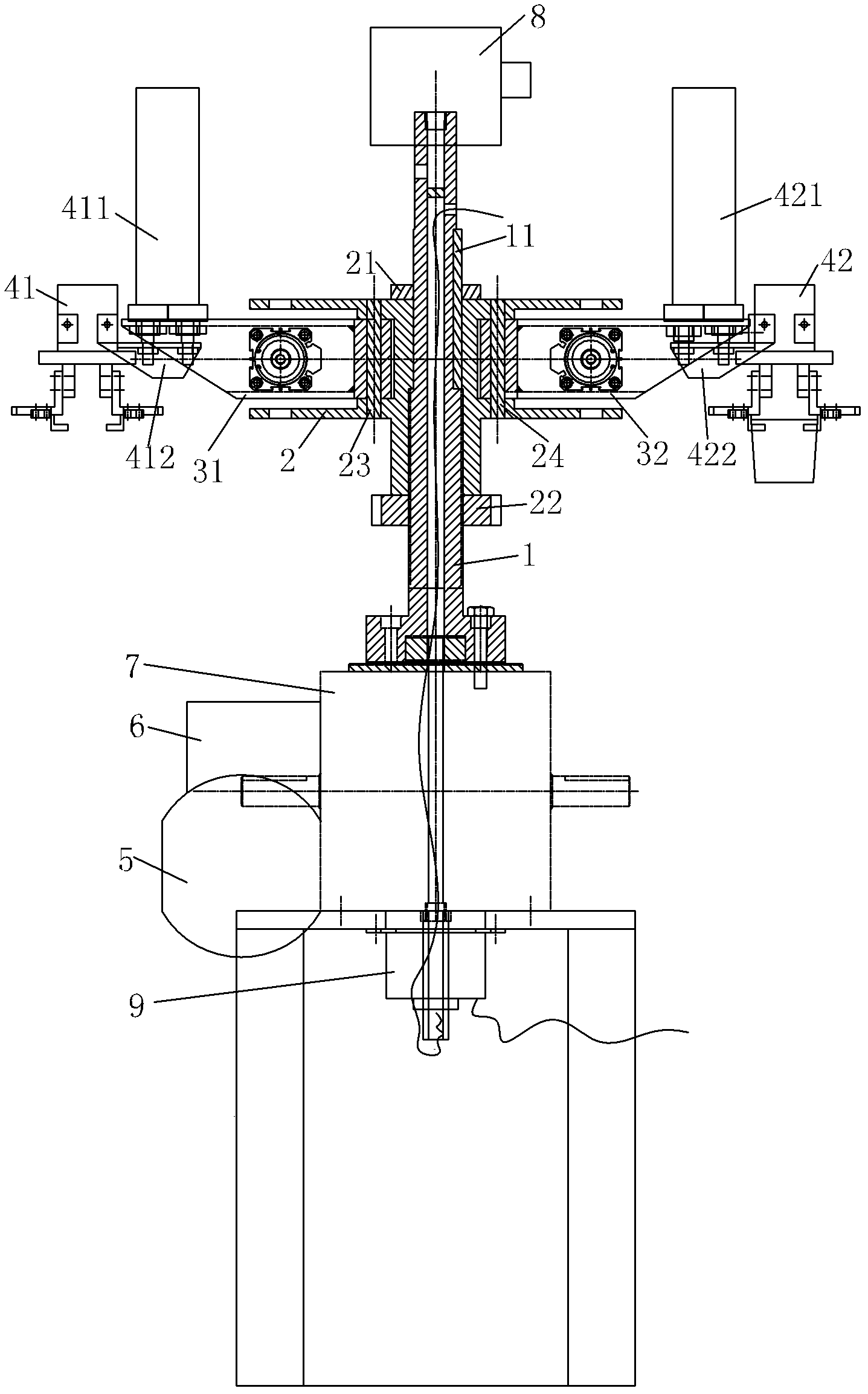
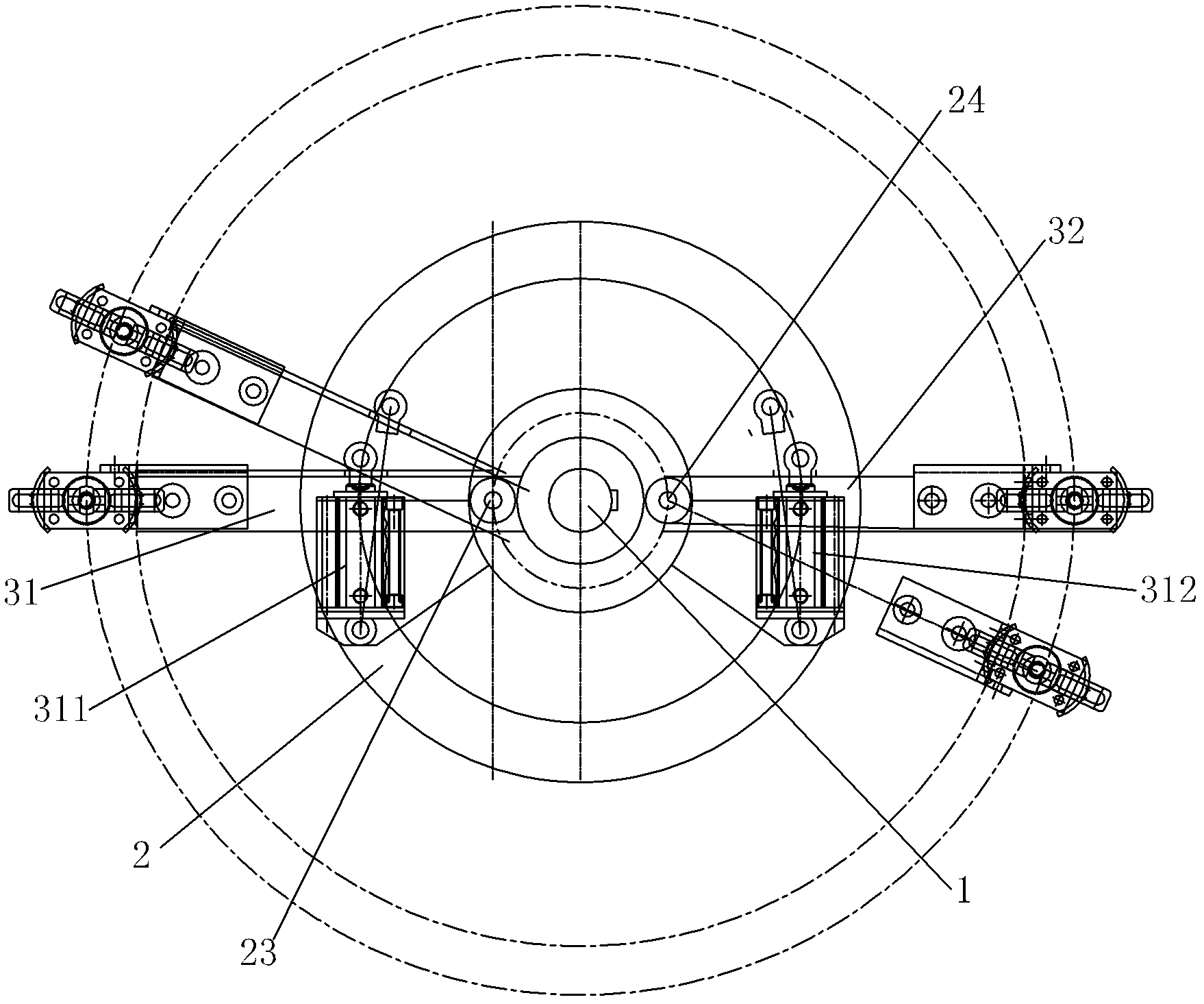
[0015] Such as figure 1 As shown, the cup taking machine of the present invention includes a rotating central axis 1, a sliding sleeve 2, first and second mechanical arms 31, 32, first and second air fingers 41, 42, an asynchronous motor 5, a worm gear reducer 6, a split Device 7, rotary joint 8, conductive slip ring 9, sliding sleeve 2 is set on the rotating central shaft 1, and there is a sliding positioning key 11 between the sliding sleeve 2 and the rotating central shaft 1, on the rotating central shaft 1, on the sliding sleeve 2. Upper and lower lock nuts 21 and 22 are screwed on the upper and lower ends respectively. The sliding sleeve 2 has two upper and lower discs. The sliding sleeve 2 is hinged with first and second hinge pins 23 and 24 respectively. Two mechanical arms 31, 32, the first and second mechanical arms 31, 32 are located between the upper and lower discs of the sliding sleeve 2, the distances from the first and second hinge pins 23, 24 to the center of t...


PUM


Abstract

A cup fetching machine belongs to the technical field of glass industries, and comprises a rotary center shaft, a sliding sleeve, first and second mechanical arms, first and second pneumatic fingers, a driving motor, an intermittent drive device, a rotary joint and a conductive slip ring, wherein the sliding sleeve is sleeved on the rotary center shaft; the first and the second mechanical arms are respectively connected to the sliding sleeve; first and second double bar extending cylinders are respectively fixed at free ends of the first and the second mechanical arms; the first and the second pneumatic fingers are respectively fixed on piston rods of the first and the second double bar extending cylinders; the intermittent drive device is connected with one end of the rotary center shaft; the rotary joint is connected with the other end of the rotary center shaft; the first and the second double bar extending cylinders are respectively connected with electromagnetic directional valves; compressed air source pipelines of the electromagnetic directional valves are connected with a rotating connector on the rotary joint; a static connector on the rotary joint is connected with a compressed air pipe network; circuit parts of the electromagnetic directional valves are respectively connected with a rotor part of the conductive slip ring; and a stator part of the conductive slip ring is connected with a control device. The cup fetching machine has the advantages that the cup fetching efficiency is greatly improved.

Description

technical field [0001] The invention relates to an automatic cup taking device after the glass cup is formed in the glass industry. Background technique [0002] At present, the cup taking machine used in the glass industry is a one-hand swinging cup taking machine, and there must be a useless work in the round-trip process of the one-handed swinging cup taking machine. Due to the low efficiency of the supporting cup taking machine, it eventually leads to The speed of the glass press upstream of the cup remover cannot be increased. Simultaneously, because the position of placing the cup after taking the cup is fixed in the existing cup machine, it cannot be matched with the double-station glass mouth dryer located downstream of the cup machine, resulting in the inability of the double-station glass mouth dryer. play a role, resulting in waste of resources and low production efficiency. Contents of the invention [0003] The object of the present invention is to provide a...

Claims


Application Information

Patent Timeline
Patent Type & Authority Applications(China)
IPC IPC(8): B65G47/91
Inventor 刘亢
Owner 刘亢
Learn More