
Cooling air introducing structure for V-shaped belt type continuously variable transmission

A technology of continuously variable transmission and cooling air, applied in motorcycles, motor vehicles, bicycles, etc., can solve problems such as large protrusions, and achieve the effects of preventing dust intrusion, ensuring wiring space, and good ventilation

Active Publication Date: 2014-07-09
HONDA MOTOR CO LTD
View PDF11 Cites 0 Cited by
  • Summary
  • Abstract
  • Description
  • Claims
  • Application Information

AI Technical Summary

Problems solved by technology

In addition, the cooling air introduction structure protrudes relatively toward the side of the vehicle and above the power unit

Method used


Image

  • Cooling air introducing structure for V-shaped belt type continuously variable transmission
  • Cooling air introducing structure for V-shaped belt type continuously variable transmission
  • Cooling air introducing structure for V-shaped belt type continuously variable transmission

Examples


Embodiment Construction

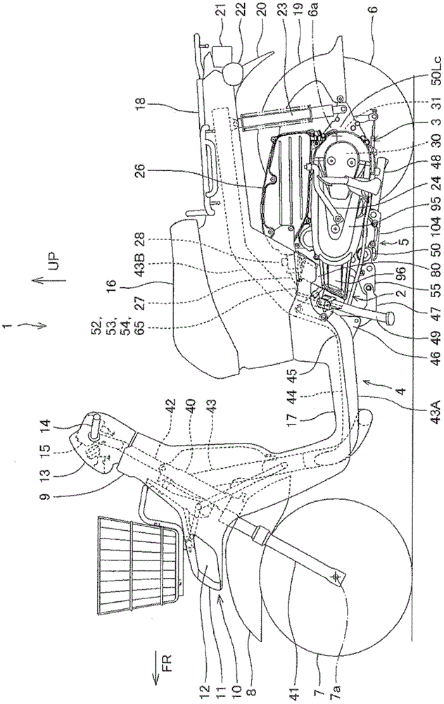
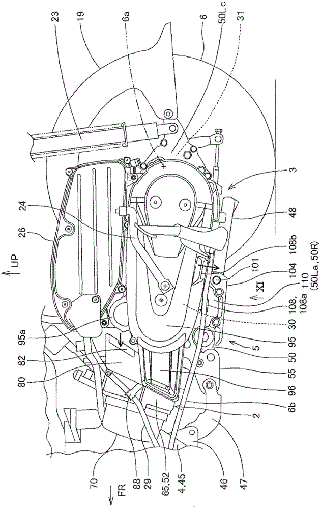
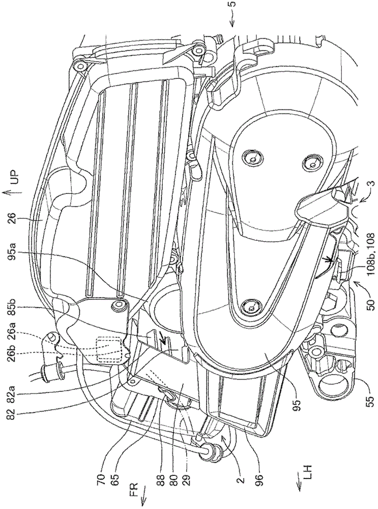
[0086] Below, based on Figure 1 to Figure 11 A cooling air introduction structure of a V-belt type continuously variable transmission according to an embodiment of the present invention will be described.

[0087] It should be noted that the descriptions in this specification and the directions such as front, rear, left, right, up, and down within the scope of the claimed invention all refer to the state in which the power unit of the embodiment of the present invention is installed on a vehicle, especially a small vehicle such as a two-wheeled motor vehicle. down, in the direction the vehicle is facing. In the drawings, arrow FR indicates the front of the vehicle, LH indicates the left side of the vehicle, RH indicates the right side of the vehicle, and UP indicates the upper side of the vehicle.

[0088] In addition, in the figure, the small black arrows schematically indicate the flow direction of the cooling air of the V-belt type continuously variable transmission, and ...


PUM


Abstract

The present invention provides a cooling air introducing structure for a V-shaped belt type continuously variable transmission, which is capable of reducing invasion of dust and so on, and restraining protruding towards a side of a vehicle body and an upward side of a power unit. In the power unit (5) at which a side is provided with the V-shaped belt type continuously variable transmission (30) of a rear wheel (6) of a vehicle (1), a cylinder part (52) of a combustion engine (2) covered by a cooling cap (65) is arranged from a crankshaft (51) of a drive pulley (33) provided with the V-shaped belt type continuously variable transmission (30) towards a front side of the vehicle, the cooling air is introduced into a cooling air passage (90) arranged at a side of a cooling fan (93) at an outer side surface of the drive pulley (33), the cooling air passage (90) is formed by connecting with a speed changing chamber (32) containing the V-shaped belt type continuously variable transmission (30) and communicating with a cooling air pipeline (80) extending towards the front side of the vehicle, an upstream side of the cooling air pipeline bends backwards after bending upwards along a side surface of the cooling cap to form a ]-shaped, and a cooling air introduction port (82) facing to a rear side of the vehicle is also provided.

Description

technical field [0001] The present invention relates to a cooling air introduction structure for a V-belt type continuously variable transmission of a power unit mounted on a small vehicle such as a motorcycle. Background technique [0002] At present, in a V-belt type continuously variable transmission installed on the side of the rear wheel of a vehicle such as a motorcycle, when cooling air is introduced into the power unit case housing the V-belt type continuously variable transmission, in order to To prevent the intrusion of foreign matter such as dust, a cooling air introduction passage opening toward the rear of the vehicle to form a cooling air introduction port can be provided on the top of the power unit, for example, the technical solutions disclosed in the following patent document 1 and the like. [0003] Patent Document 1: (Japan) Publication No. 63-17695 ( Figure 4 , Figure 5 ) [0004] However, if, as shown in the above-mentioned Patent Document 1, a cool...

Claims


Application Information

Patent Timeline
Patent Type & Authority Patents(China)
IPC IPC(8): B62K11/00
Inventor 元木雅一猪狩武男山口聪藤登博
Owner HONDA MOTOR CO LTD
Learn More