
Self-locking adjusting device and method for using same

An adjustment device and self-locking technology, applied in the field of mechanical processing, can solve the problems of cumbersome operation, time-consuming and laborious, and difficult to guarantee accuracy.

Active Publication Date: 2014-06-25
CITIC HEAVY INDUSTRIES CO LTD
View PDF3 Cites 0 Cited by
  • Summary
  • Abstract
  • Description
  • Claims
  • Application Information

AI Technical Summary

Problems solved by technology

The positioning technology of the workpiece on the T-slot workbench, the traditional method is to make the corresponding self-locking base on the workbench according to the distance between two adjacent T-slots, and use at least two T-shaped bolts to lock the self-locking base. Tightly fixed to the workbench, this method is cumbersome to operate, time-consuming and labor-intensive, and the accuracy is difficult to guarantee, which has great limitations in application

Method used


Image

  • Self-locking adjusting device and method for using same
  • Self-locking adjusting device and method for using same
  • Self-locking adjusting device and method for using same

Examples


Embodiment Construction

[0024] The technical solution of the present invention will be described in further detail below with reference to the accompanying drawings and embodiments.

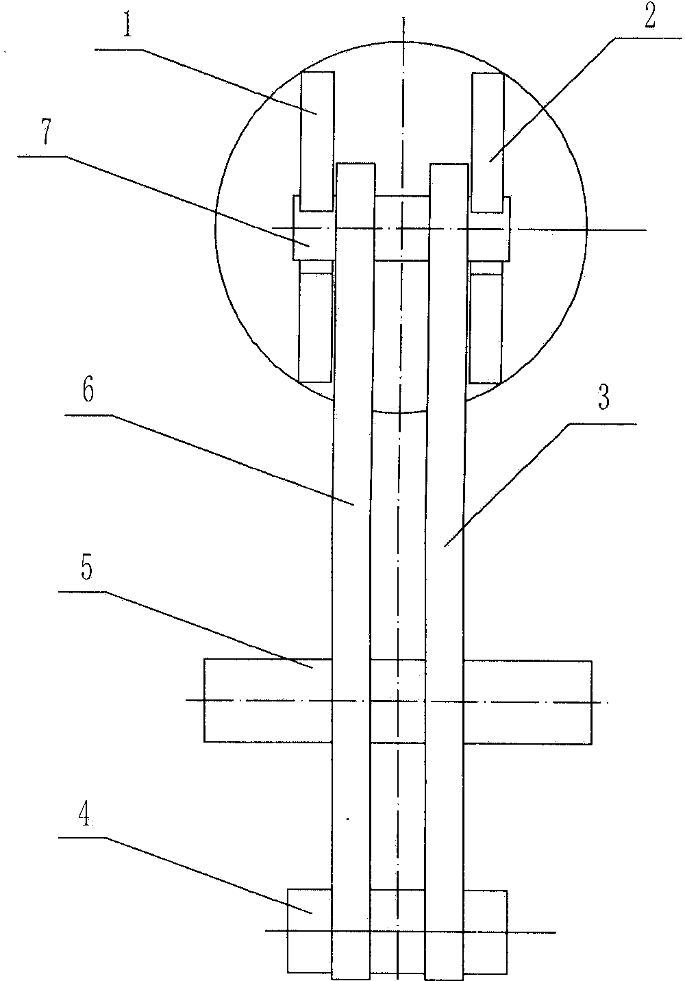
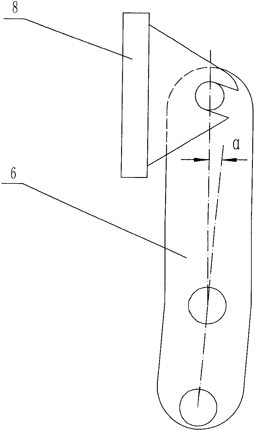
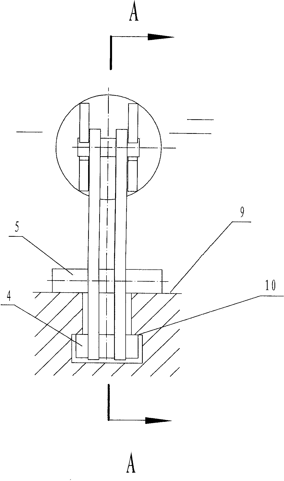
[0025] Such as figure 1 , 2 As shown, the self-locking adjustment device mainly includes a lever arm and a top seat, and the lever arm is composed of mutually parallel support plates A 6, support plates B 3 and pin shafts connecting the two support plates, support plates A, The lower part of the support plate B is bent inward, and the upper part, the bent part and the lower part of the two support plates are respectively provided with pin hole A, pin hole B and pin hole C, and the pin shaft A 7, the pin shaft B 5 and the pin shaft C 4 are respectively pierced In the pin hole A, pin hole B, and pin hole C of the two support plates and welded together with the support plate; Composition, one side of the connecting plate is provided with a notch matching with the pin shaft A; the pin shaft A is pierced through the notche...


PUM


Abstract

The invention discloses a self-locking adjusting device and a method for using the same. The self-locking adjusting device mainly comprises a lever arm and a top seat. The lever arm comprises two mutually parallel support plates and three pins connected with the two support plates, the lower portions of the support plates are bent inwards, pin holes are arranged on the upper portions, at bent positions and on the lower portions of the support plates respectively, and the three pins penetrate into the pin holes of the two support plates respectively and are integrally welded with the support plates. The top seat comprises a bottom plate and two connecting plates parallelly arranged on the bottom plate, notches matched with the pins penetrating into the pin holes on the upper portions of the support plates are arranged on one side of each connecting plate, and the pins penetrating into the notches of the two connecting plates and the pin holes of the two support plates are integrally welded. The method for using the self-locking adjusting device includes: mounting the pins on the lower portions of the support plates in a T-shaped groove of a worktable; tightly attaching the bent positions of the pins to the surface of the worktable to realize self-locking; and driving a workpiece to move along the T-shaped groove of the worktable by the aid of a jack serving as power to adjust micro-displacement of the workpiece.

Description

technical field [0001] The invention belongs to the technical field of mechanical processing, and relates to an adjustment device, in particular to a self-locking adjustment device for adjusting the displacement of a workpiece along the length direction of a T-shaped groove of a workbench and a use method thereof. Background technique [0002] With the rapid development of the world's manufacturing industry, large mining mills have become the leading products in the metallurgical and building materials markets. However, the bolt holes for fixing the liner on the mill cylinder have been processed by CNC floor boring and milling machines after the cylinder has been rolled, formed and welded for a long time. The cost is very high. In order to improve production efficiency and reduce process costs, the In the case of product use requirements, we strive to achieve the performance of the product by using some advanced mechanical equipment, such as CNC gantry drilling machines, etc...

Claims


Application Information

Patent Timeline
Patent Type & Authority Patents(China)
IPC IPC(8): B23Q3/18B23B47/00
Inventor 段世新肖德政赵朝辉乔岩莉王志平卢雷胜李利霞李园园闫智卫赵岩黄玉豪
Owner CITIC HEAVY INDUSTRIES CO LTD
Learn More