Disc vacuum filter with independent adsorption system and independent dewatering system

A vacuum filter, disc type technology, applied in filtration and separation, mobile filter element filters, chemical instruments and methods, etc., can solve the problems of overloaded stop of the stirring shaft, increased enterprise cost, uneven slurry concentration, etc. Stable, energy-saving, and unbreakable effects

Active Publication Date: 2014-02-26
鞍山嘉丰科技有限公司
View PDF5 Cites 0 Cited by
  • Summary
  • Abstract
  • Description
  • Claims
  • Application Information

AI Technical Summary

Problems solved by technology

In addition, the filter fan structure of the existing disc vacuum filter itself also has design defects, and a large vacuum power source is also required in the process of adsorption and dehydration, which not only causes waste of energy, but also increases the cost of the enterprise
In addition, the stirring device of the existing disc vacuum filter is a paddle-type structure. Because there is a large distance between this structure and the filter disc, some areas cannot be stirred when stirring, so that the concentration of the slurry in the tank is reduced. Unevenness is not conducive to the adsorption of the filter fan. When encountering the slurry with large filter particles and fast sedimentation speed, it is easy to cause sedimentation and accumulation, and the agitator shaft is overloaded and stopped. Moreover, the agitator shaft needs to extend out of the tank, so that the seal Not tight, prone to slurry leakage

Method used


Image

  • Disc vacuum filter with independent adsorption system and independent dewatering system
  • Disc vacuum filter with independent adsorption system and independent dewatering system
  • Disc vacuum filter with independent adsorption system and independent dewatering system

Examples


Embodiment Construction

[0032] The specific implementation manner of the present invention will be further described below in conjunction with the accompanying drawings.

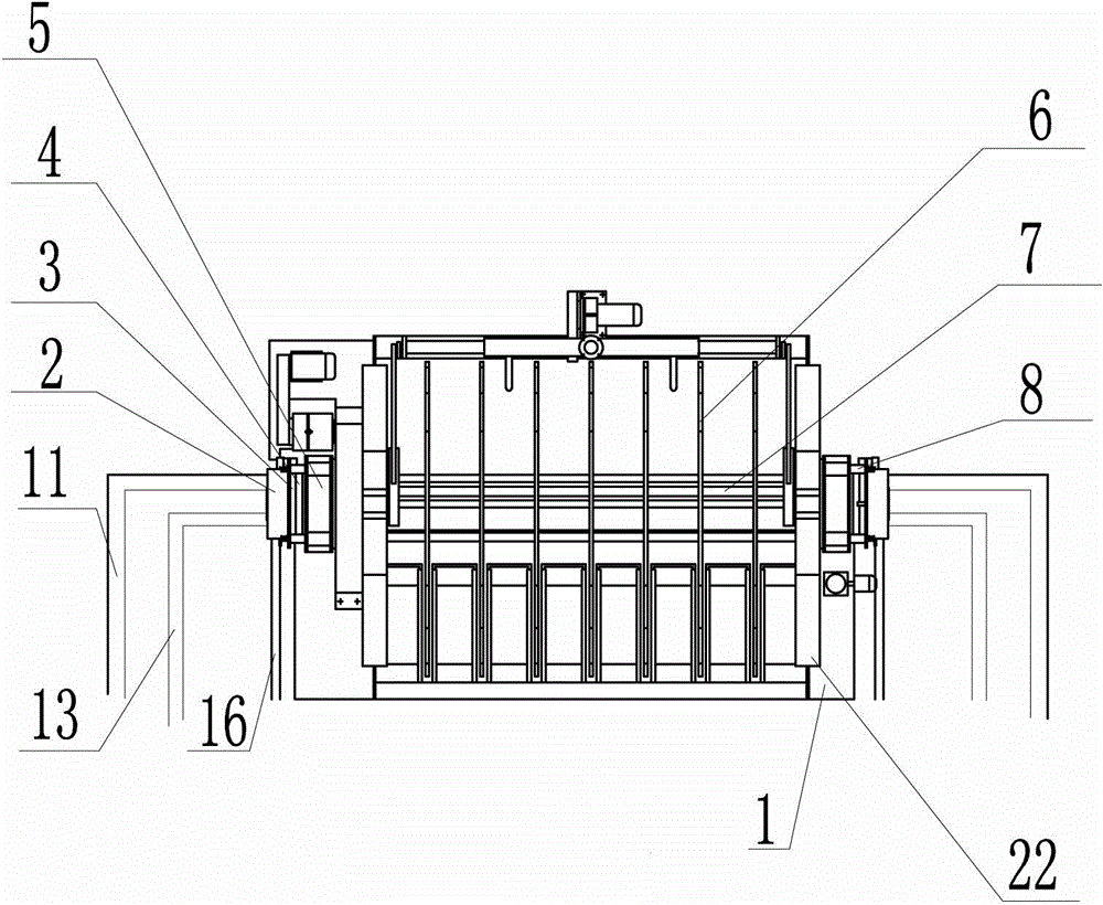
[0033] Such as figure 1 , 2 As shown, a disc vacuum filter with independent adsorption and independent dehydration system includes a tank body 1 with an overflow port, a slurry discharge port and a discharge port, and bearing assemblies 5 arranged at both ends of the tank body 1 , the main shaft system 7 arranged between the two bearing assemblies 5, the air discs 4 which are fixed on both ends of the main shaft system 7 and rotate synchronously with the main shaft system 7, are adjacent to the two air discs 4 respectively Two fixed distribution head devices connected, a group of filter discs 6 arranged on the main shaft system 7, a stirring device 22 arranged in the tank body 1, and a transmission mechanism connected with the main shaft system 7.

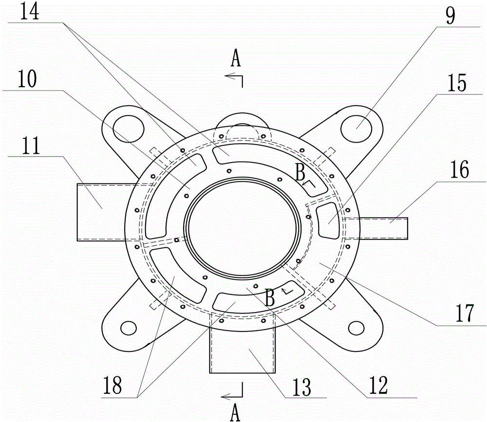
[0034] Such as figure 1 , 3 , 4, and 5, it is characterized in that the fixed d...


PUM

PropertyMeasurementUnit
lengthaaaaaaaaaa

Abstract

The invention discloses a disc vacuum filter with an independent adsorption system and an independent dewatering system, which comprises a tank body, a bearing assembly, a spindle, an air dislocation disc, two fixing distribution head devices, a filter disc, a stirring device and a transmission device. The disc vacuum filter is characterized in that each fixing distribution head device comprises a distribution head, a distribution disc and a connection lug, wherein a cavity in the distribution head consists of an adsorption cavity, a dewatering cavity and a discharging cavity, the adsorption cavity is connected with a vacuum adsorption pipeline which is connected with an inlet end of a vacuum pump I, the dewatering cavity is connected with a vacuum dewatering pipeline which is connected with an inlet end of a vacuum pump II, and the discharging cavity is connected with a discharging pipeline which is connected with an outlet end of the vacuum pump I and the vacuum pump II. The disc vacuum filter is respectively provided with the vacuum adsorption system and the vacuum dewatering system which respectively select vacuum power sources matched with the vacuum adsorption system and the vacuum dewatering system to enable total energy consumption of the vacuum power sources to be reduced by 50%-60%.

Description

technical field [0001] The invention belongs to the technical field of disc vacuum filter equipment, and in particular relates to a disc vacuum filter with independent adsorption and independent dehydration systems. Background technique [0002] Disc vacuum filter is a device that uses vacuum as the filtering power to separate the slurry from solid to liquid. It is suitable for the dehydration of iron concentrates, tailings, non-ferrous metal concentrates and tailings, and is also suitable for coal washing plants, non-metallic Dehydration operations in mining, chemical and environmental protection fields. In the prior art, the vacuum adsorption system and the vacuum dehydration system of the disc vacuum filter are completed in one pipeline system, that is, the adsorption and dehydration processes are operated by the same vacuum power source, and the vacuum source requirements for the adsorption and dehydration processes are But it is different: the adsorption process requir...

Claims


Application Information

Patent Timeline
Patent Type & Authority Patents(China)
IPC IPC(8): B01D33/23B01D33/62B01D33/68
Inventor 孙宏越
Owner 鞍山嘉丰科技有限公司
Why Eureka
Try Eureka