
Hybrid hydraulic excavator

A hybrid power and excavator technology, applied in the direction of earth movers/shovels, mechanical equipment, fluid pressure actuating devices, etc., can solve the problems of unreleased energy and difficulty in component installation, and achieve energy reduction and lightening. Effect of load pressure

Active Publication Date: 2012-06-27
临沂山重挖掘机有限公司
View PDF7 Cites 30 Cited by
  • Summary
  • Abstract
  • Description
  • Claims
  • Application Information

AI Technical Summary

Problems solved by technology

For example, the invention patent with the publication number CN101037869A discloses a hybrid construction machine, which uses the engine to connect the hydraulic pump and the generator / motor in parallel through the power distributor, and drives the rotary motor by the accumulator, but due to limited engineering The mechanical installation space makes the installation of components more difficult. In terms of energy recovery, only the rotational kinetic energy is regeneratively recovered, braked and recovered, and the potential energy of the lowering of the boom is not recovered.
The invention patent with the publication number CN101408212A discloses an energy recovery system for the actuators of hybrid construction machinery, which adopts a parallel hybrid drive structure and introduces a boom with recovery motors, accumulators and generators as core components. The energy recovery system recovers the potential energy of the lowering boom. Although it recovers the potential energy of the boom, since the outlet of the accumulator is directly connected to the main pump, when the pressure of the hydraulic system is higher than the pressure of the accumulator, the energy storage The energy stored in the device cannot be released when the boom is lowered

Method used


Image

  • Hybrid hydraulic excavator
  • Hybrid hydraulic excavator
  • Hybrid hydraulic excavator

Examples


Embodiment Construction

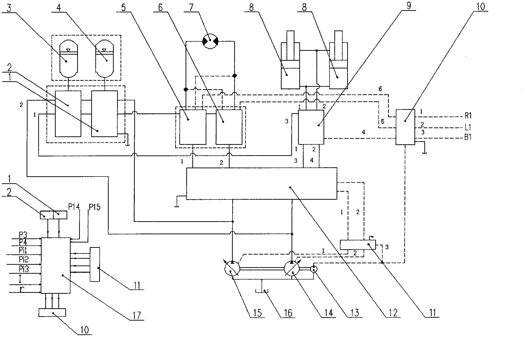
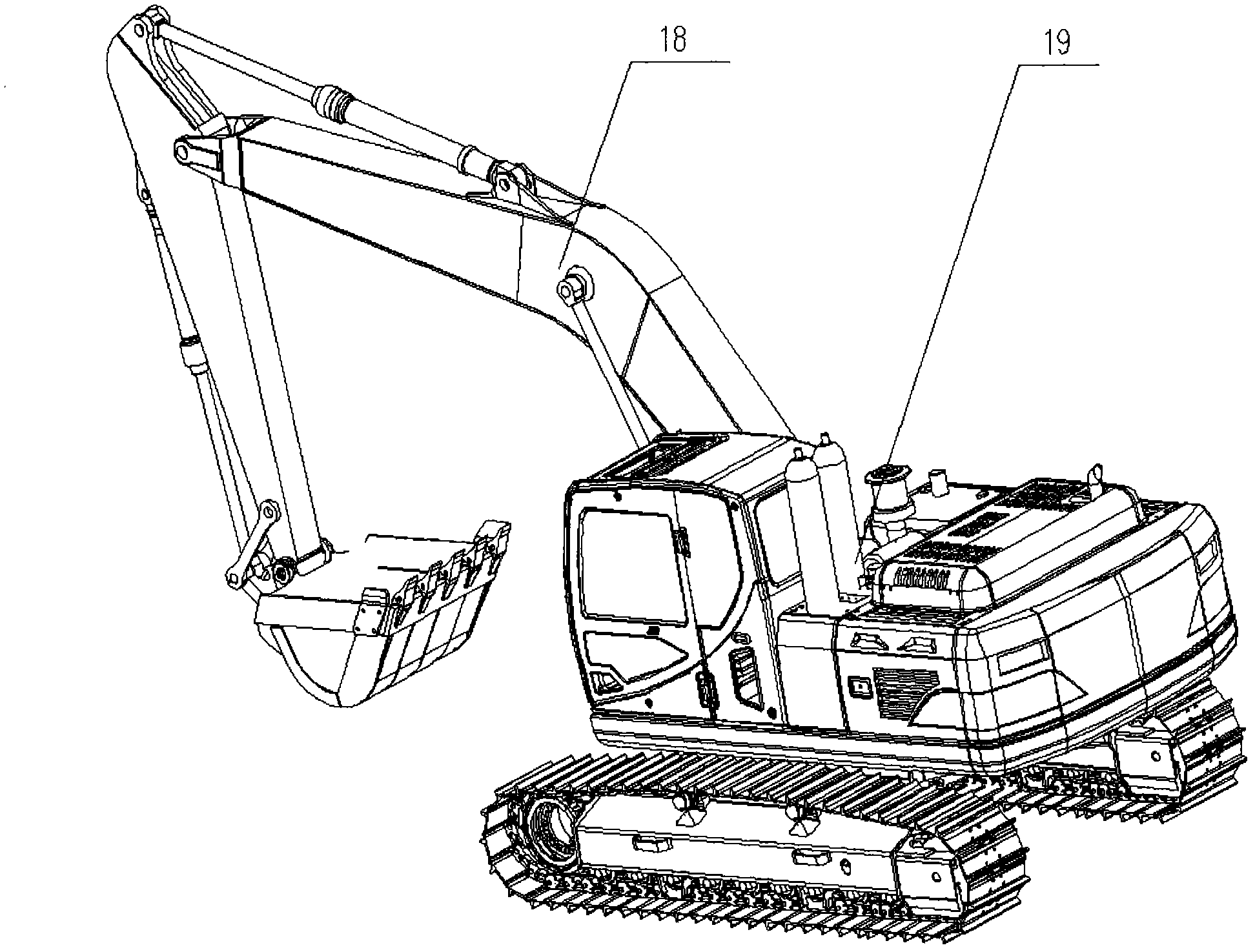
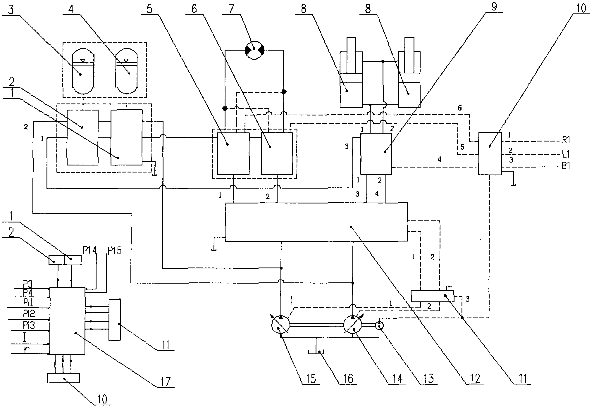
[0025] refer to figure 1 and figure 2 , the control system of the hybrid excavator of the present invention includes a first energy release valve block 1, a second energy release valve block 2, a first accumulator 4, a second energy accumulator 3, and a first rotary energy recovery valve block 5 , the second rotary energy recovery valve block 6, the rotary motor 7, the boom cylinder 8, the boom energy recovery valve block 9, the pilot control valve block 10, the pump control system valve block 11, the multi-way valve 12, the pilot hydraulic pump 13, The first main hydraulic pump 14, the second main hydraulic pump 15, the hydraulic oil tank 16, the hybrid controller 17;

[0026]The outlets of the first main hydraulic pump 14 and the second main hydraulic pump 15 are connected to the oil inlet of the multi-way valve 12 through rubber hoses, and the first pilot oil port of the multi-way valve 12 is connected to the valve block of the pump control system through rubber hoses. 1...


PUM


Abstract

The invention discloses a hybrid hydraulic excavator, which comprises a control system. The control system comprises a first energy release valve block (1), a second energy release valve block (2), a first energy accumulator (4), a second energy accumulator (3), a first rotary energy recovering valve block (5), a second rotary energy recovering valve block (6), a rotary motor (7), a movable arm oil cylinder (8), a movable arm energy recovering valve block (9), a guide control valve block (10), a pump-controlled system valve block (11), a multi-way valve (12), a guide hydraulic pump (13), a first main hydraulic pump (14), a second main hydraulic pump (15), a hydraulic oil tank (16) and a hybrid controller (17). The hydraulic excavator can automatically judge and recover braking energy to a rotary system motion state at a deceleration braking energy recovering stage and simultaneously enable an engine to always work at an efficient interval.

Description

technical field [0001] The invention relates to a construction machine with a control system, in particular to a hydraulic excavator with a hydraulic slewing deceleration braking system and a recovery of the descending potential energy of an actuator. Background technique [0002] Hydraulic excavators are used in a wide range of applications and have a lot of energy losses. Research on the energy saving of hydraulic excavators has great economic value and very important practical significance. The traditional hydraulic excavator slewing system often achieves the braking effect through reverse back pressure when decelerating and braking. The valve returns to the oil tank, and the downward potential energy of the boom cylinder is converted into the heat energy of the oil being pressed; it will cause the hydraulic system to heat up, produce various hydraulic system defects such as cavitation, and reduce the life of the hydraulic system. Since the slewing action is a very frequ...

Claims


Application Information

Patent Timeline
Patent Type & Authority Applications(China)
IPC IPC(8): E02F9/22F15B21/14
Inventor 王守洪李春生王保森仲光旭戴广泰满涛张义王正磊吝宝强么鸣宇
Owner 临沂山重挖掘机有限公司
Learn More