
Industrial part conveying device

A conveying device and industrial technology, applied in conveyors, mechanical conveyors, transportation and packaging, etc., can solve problems such as poor track rigidity, affecting work efficiency, and occurrence of safety accidents, so as to achieve good overall structural rigidity and reduce Labor intensity, the effect of improving work efficiency

Inactive Publication Date: 2012-06-27
大连奥托股份有限公司
View PDF0 Cites 18 Cited by
  • Summary
  • Abstract
  • Description
  • Claims
  • Application Information

AI Technical Summary

Problems solved by technology

The conveying device with this structure has the following disadvantages: 1. The track rigidity is not good. Under the conditions of large load or high speed and large impact, the track is easy to deform, causing the pulley to fall off, affecting production or causing safety accidents
2. The noise is high. In this type of structure, the part below the pulley has a large degree of freedom, and the equipment itself has a large impact during the transmission process, resulting in relatively large noise
3. Ergonomics are poor. This type of structure requires the operator to exert a large force to pull or drag the system to run
4. The positioning is not precise and the operation is unstable. It needs to cooperate with other auxiliary positioning and guiding components to realize the grasping and placement of parts, which affects work efficiency and easily causes damage to sheet metal parts.

Method used


Image

  • Industrial part conveying device
  • Industrial part conveying device
  • Industrial part conveying device

Examples


Embodiment Construction

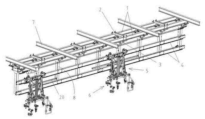
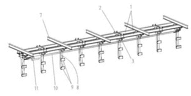
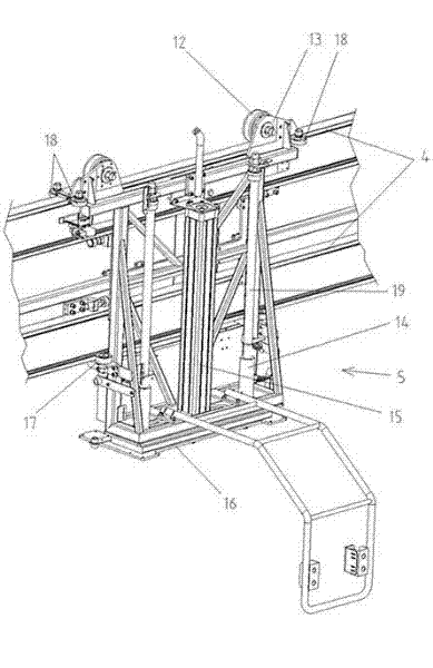
[0011] Such as figure 1 , 2 , Shown in 3: 6 is a part gripper, used for grasping parts, which belongs to the prior art part.

[0012] 1 is the main beam arranged vertically, 2 is the cross beam arranged horizontally, the cross beam 2 and the main beam 1 are fixedly connected or welded by bolts, and the main beam 1 and the cross beam 2 form the frame body of the device. Vertical beams 8 arranged at intervals are connected below the frame body, and the vertical beams 8 and the frame body are fixedly connected by bolts and connecting plates 3 .

[0013] Welding or bolting on each vertical beam 8 are connected with two track connecting plates 9 up and down, and on the track connecting plate 9, are fixed with a track 4 parallel to the main beam by bolts, and the track 4 is divided into two up and down. The tackle 5 with frame structure is suspended on the track 4, and the vertically arranged cylinder 15 connected with the pneumatic control device is housed on the tackle 5. 16 co...


PUM


Abstract

The invention discloses an industrial part conveying device, which comprises part grippers. A frame consists of longitudinal main beams and horizontal crossbeams, vertical beams are connected below the frame at intervals, rails parallel to the main beams are fixed onto the vertical beams, sliding trolleys are hung on the rails, a cylinder is mounted on each sliding trolley, the tip of a piston rod matched with the corresponding cylinder is connected with a bottom plate, guide columns are connected onto each bottom plate, guide cylinders sleeved onto the guide columns are arranged on each sliding trolley, and each part gripper is mounted on the corresponding bottom plate. Compared with the prior art, the industrial part conveying device is fine in integral structure rigidity, not easy to deform, safe, reliable, low in noise in operation, high in stability and not easy to shake when hoisting workpieces for horizontal movement, and accurate in place, so that operation efficiency is improved, labor intensity of operators is reduced, and yield is high.

Description

technical field [0001] The invention relates to a conveying device, in particular to a conveying device for industrial parts, which is mainly used for conveying the sheet metal parts and components of the body-in-white in the field of automobile welding. Background technique [0002] At present, the device structure for the transmission of body-in-white sheet metal parts and components in the automobile welding equipment is to install a C-shaped track through a steel structure above the workshop, hang a mobile car on the C-shaped track, and install an electric hoist on the mobile car. The parts gripper is hoisted by the electric hoist, and the parts to be welded are grasped by the parts gripper, lifted by the electric hoist, and moved on the C-shaped track with the moving vehicle, and the parts are sent from one station to another. bit. The delivery device of this structure has the following disadvantages: 1. The track rigidity is not good. Under the conditions of greater l...

Claims


Application Information

Patent Timeline
Patent Type & Authority Applications(China)
IPC IPC(8): B65G35/00
Inventor 白金国
Owner 大连奥托股份有限公司
Learn More