Cutter shaft structure for paper cutter of toilet paper folding machine

A paper cutter and folding machine technology, applied in metal processing and other directions, can solve the problems that affect the processing and finished product quality, increase the manufacturing cost of paper cutters, and have particularly high requirements, so as to delay labor and time, prolong service life, and reduce use. cost effect

Inactive Publication Date: 2012-06-27
郭肖凡
View PDF6 Cites 0 Cited by
  • Summary
  • Abstract
  • Description
  • Claims
  • Application Information

AI Technical Summary

Problems solved by technology

The specific situation is that the paper cutter is installed vertically on the cutter shaft, and there is an angle between the paper cutter and the strip knife. At the same time, the middle part of the paper cutter and the strip knife is designed as an arc shape. Since the contact surface between the paper cutter and the strip cutter is small at the same time, the above-mentioned beneficial effects can be achieved. However, in order to meet the rigidity requirements during operation, the requirements for the materials used for the paper cutter are particularly high, which greatly improves the efficiency of paper cutting. The manufacturing cost of the knife, otherwise the knife will often break, which will seriously affect the subsequent processing and the quality of the finished product

Method used


Image

  • Cutter shaft structure for paper cutter of toilet paper folding machine
  • Cutter shaft structure for paper cutter of toilet paper folding machine
  • Cutter shaft structure for paper cutter of toilet paper folding machine

Examples


Embodiment Construction

[0033] The present invention will be further described below in conjunction with specific examples.

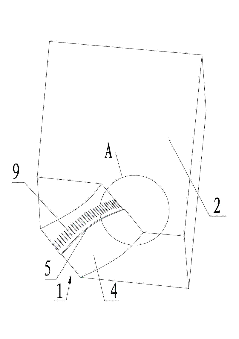
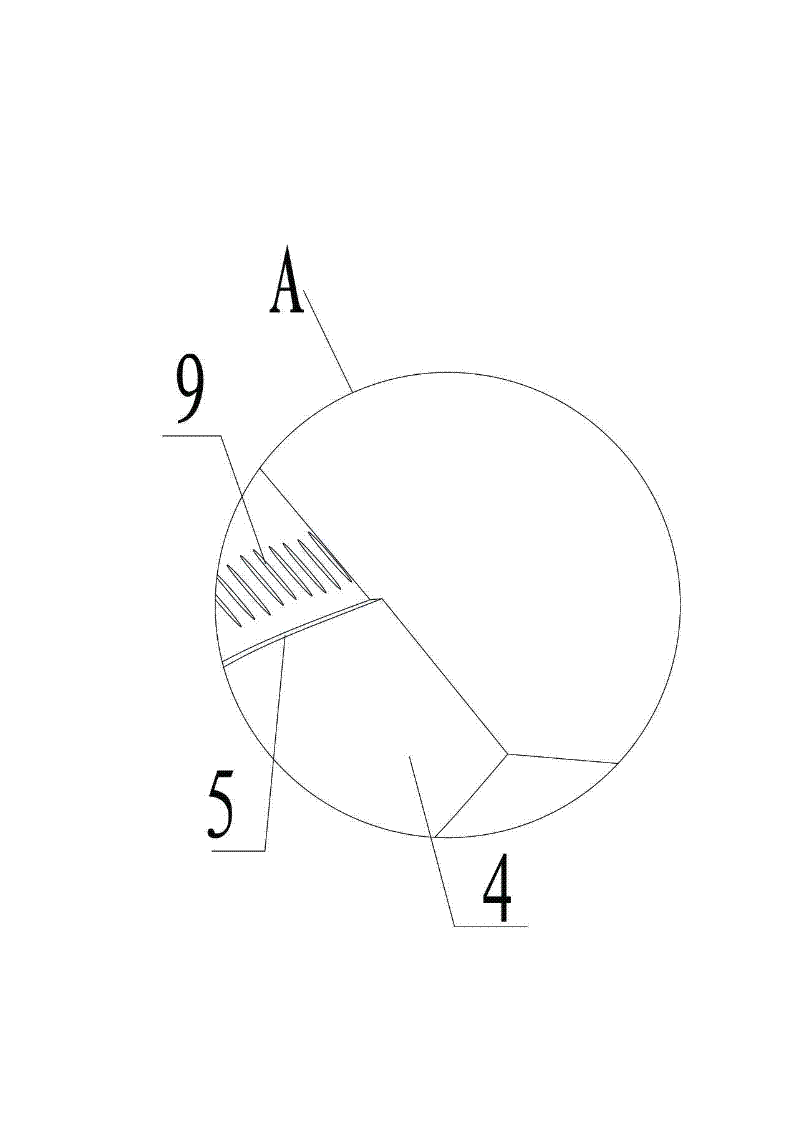
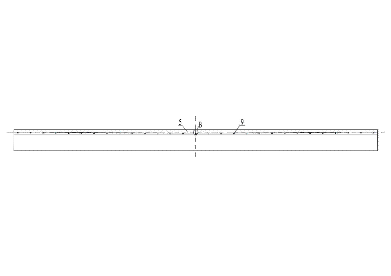
[0034] See attached figure 1 to attach Figure 15 As shown, the paper cutter shaft structure of the toilet paper folding machine described in this embodiment includes a knife shaft body 2, wherein the paper cutter installation position 1 of the knife shaft body 2 is in close contact with the paper cutter blade surface The combined surface is an oblique cut surface along the length direction of the knife shaft body, and the oblique cut surface forms a curved first inferior arc surface 4 inwardly, and the two sides of the vertical centerline of the first inferior arc surface 4 are symmetrical to each other; the paper cutter The surface of the installation position 1 and the back of the paper cutter is the second inferior arc surface 5 that makes the back of the paper cutter form an arched back, and the two sides of the vertical center line of the second inferior arc surface 5 a...


PUM


Abstract

The invention provides a cutter shaft structure for a paper cutter of a toilet paper folding machine. The cutter shaft structure comprises a cutter shaft body, wherein a surface on which a paper cutter mounting position of the cutter shaft body is attached with the cutter face of the paper cutter is a diagonal plane along a length direction of the cutter shaft body; the diagonal plane inwards forms a curved first minor arc surface; a surface on which the paper cutter mounting position is attached with the cutter back of the paper cutter is a second minor arc surface which makes the cutter back of the paper cutter form an arch back; and the first minor arc surface is intersected with the second minor arc surface at the same time. Due to the scheme, the cutter shaft structure has the advantages of low manufacturing cost of the paper cutter, high paper cutting efficiency, low paper cutting noise, convenience for disassembly and assembly of the paper cutter, short time and the like; and the paper cutter can effectively cut paper and does not have a state that the paper is connected and cannot be cut off due to the time-sharing point contact between the paper cutter and a bar cutter.

Description

technical field [0001] The invention relates to the technical field of paper product processing equipment, in particular to a paper cutter shaft structure of a toilet paper folding machine. Background technique [0002] Traditional toilet paper folding machines generally use the upper and lower opposite and rotating cutter shafts and folding rollers to cooperate with paper cutting to achieve the purpose of cutting paper. Complete cutting, when the lower paper cutter on the folding roller adopts a strip knife, the paper cutter on the knife shaft must also use a strip knife. If the strip knife is not used, there will be continuous paper cutting, but when two Both of them are strip-shaped knives. When touching the tangent, the knife surfaces are in contact at the same time. For multi-layer paper with a certain thickness, there will also be a situation that it cannot be completely cut, so that the next step cannot be completed; therefore, the above-mentioned cutting The paper m...

Claims


Application Information

Patent Timeline
Patent Type & Authority Applications(China)
IPC IPC(8): B26D7/26B26D1/40
Inventor 郭肖凡
Owner 郭肖凡
Why Eureka
Try Eureka