Contact-type ice hockey shooting training device based on gravity sensor
A technology of gravity sensor and training device, applied in the field of training equipment
- Summary
- Abstract
- Description
- Claims
- Application Information
AI Technical Summary
Problems solved by technology
Method used
Image
Examples
specific Embodiment approach 1
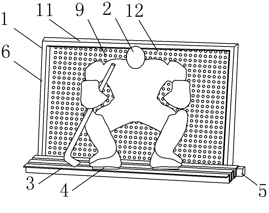
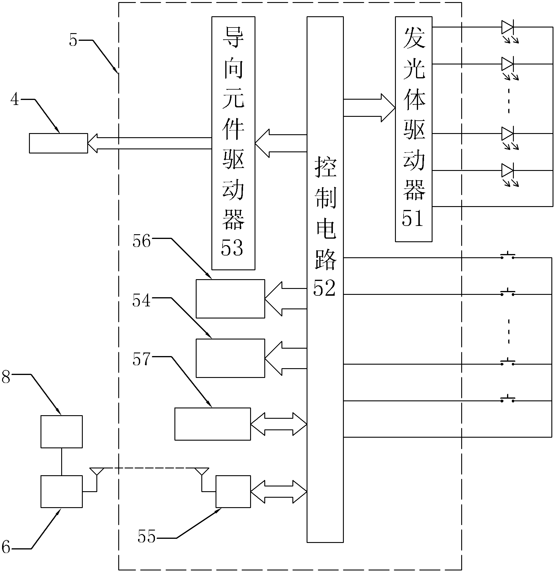
[0018] Specific implementation mode one: combine Figure 1 to Figure 3 To describe this embodiment,
[0019] This embodiment includes a hockey stick, a goal 1, a simulated goalkeeper 2, a guide rail 3, a guide element 4, an electric control device 5, a radio frequency signal transmitter 6, a gravity sensor 8, a plurality of LED light-emitting points 9 and a plurality of micro switches 7 ;
[0020] The goal 1 comprises a goal outer frame 11 and a goal stopper 12,
[0021] The size and specification of the goal outer frame 11 is the same as that of the ice hockey goal outer frame, and the goal baffle 12 is installed in the goal 1;
[0022] A guide rail 3 is arranged on the front goalkeeper control line of the goal 1, and the guide rail 3 is connected with a guide element 4, and the simulated goalkeeper 2 is installed on the guide element 4,
[0023] The goal stopper 12 is a sheet with a thickness,
[0024] The goal stopper 12 is composed of a light-transmitting surface layer...
specific Embodiment approach 2
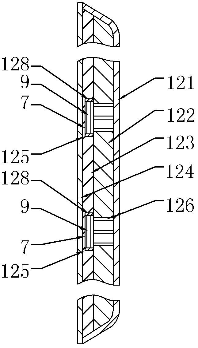
[0039] Specific implementation mode two: combination figure 2 This embodiment is described. The difference between this embodiment and the above-mentioned specific embodiments is that each LED luminous point 9 is provided with a luminous point protective cover 128 . Other compositions and connection modes are the same as the above-mentioned specific embodiment.
[0040] The light-emitting point protection cover 128 added in this embodiment is used to protect the LED light-emitting point 9 from being damaged by being hit during the training process. Each LED luminous point 9 is arranged in the luminous point protective cover 128, and when there is an external force, it is borne by the luminous point protective cover 128 to avoid the LED luminous point 9 from being stressed.
[0041] The light-emitting point protective cover 128 in this embodiment can be ring-shaped or semi-ring-shaped, and its height is greater than that of the LED light-emitting point 9 and less than or equa...
specific Embodiment approach 3
[0042]Embodiment 3: The difference between this embodiment and the above-mentioned embodiment is that the control circuit 52 is realized by a single-chip microcomputer, which is used to output control signals according to the set rules, and drives the LED light-emitting point 9 to emit light through the luminous body driver 51 .
[0043] In this embodiment, a single-chip microcomputer is used to realize the control circuit 52, and the LED light-emitting point 9 can be set according to training needs, and then cooperate with the training.
[0044] The single-chip microcomputer can be selected from existing single-chip microcomputers, such as 51 series single-chip microcomputers, AVR series single-chip microcomputers, PIC series single-chip microcomputers, 430 series single-chip microcomputers, etc., all of which can realize the functions described in this embodiment.
PUM
 Abstract
Description
Claims
Application Information
 - R&D
- Intellectual Property
- Life Sciences
- Materials
- Tech Scout
- Unparalleled Data Quality
- Higher Quality Content
- 60% Fewer Hallucinations
Browse by: Latest US Patents, China's latest patents, Technical Efficacy Thesaurus, Application Domain, Technology Topic, Popular Technical Reports.
© 2025 PatSnap. All rights reserved.Legal|Privacy policy|Modern Slavery Act Transparency Statement|Sitemap|About US| Contact US: help@patsnap.com


