Non-contact-type ice hockey shooting training device based on gravity sensor
A technology of gravity sensor and training device, applied in the field of training equipment
- Summary
- Abstract
- Description
- Claims
- Application Information
AI Technical Summary
Problems solved by technology
Method used
Image
Examples
specific Embodiment approach 1
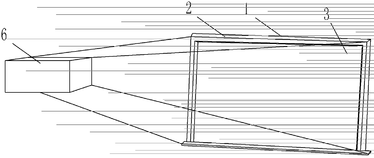
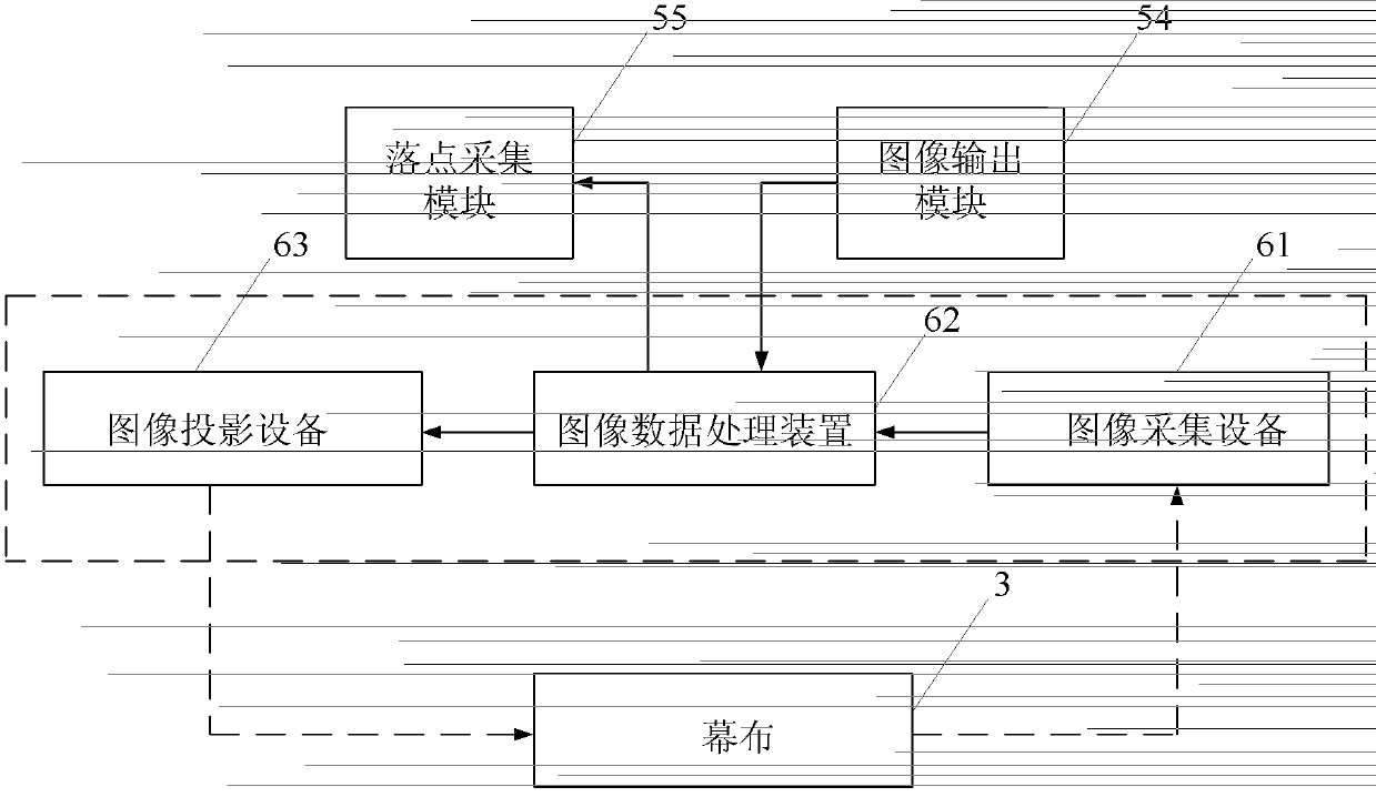
[0023] Specific implementation mode one: combine figure 1 and image 3 Describe this embodiment, the non-contact ice hockey shooting training device based on the gravity sensor described in this embodiment, it includes a hockey stick, a goal 1, an electric control device 5, an image projection system 6, a signal transmitter 7 and a gravity sensor 8;
[0024] The goal 1 includes a goal frame 2 and a curtain 3, the size of the goal frame 2 is the same as that of the ice hockey goal frame, and the curtain 3 is installed in the goal; a gravity sensor 8 and a signal transmitter are installed on the ice hockey stick Device 7, the sensing signal output end of gravity sensor 8 is connected with the sensing signal input end of signal transmitter 7,
[0025] The sensing signal input end of the electric control device 5 is connected with the sensing signal output end of the signal transmitter 7;
[0026] The image projection system 6 includes an image acquisition device 61, an image da...
specific Embodiment approach 2
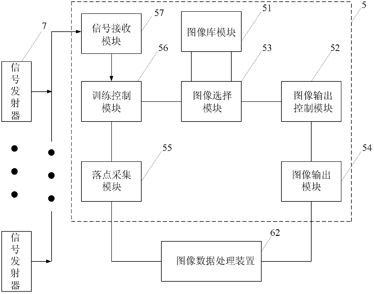
[0040] Specific implementation mode two: combination figure 2 Describe this embodiment, the difference between this embodiment and the above-mentioned specific embodiments is that the electronic control device 5 is composed of an image library module 51, an image output control module 52, an image selection module 53, an image output module 54, a landing point acquisition module 55, The training control module 56 and the signal receiving module 57 are composed; the image selection control signal output end of the training control module 56 is connected with the image selection control signal input end of the image selection module 53; the image selection control signal of the image selection module 53 The output end is connected with the image retrieval control signal input end of the image library module 51;
[0041] The image output data input end of the image selection module 53 is connected with the image output data output end of the image library module 51;
[0042] Th...
specific Embodiment approach 3
[0047] Embodiment 3: The difference between this embodiment and the above-mentioned embodiment is that the image library module 51 is used to store image information;
[0048] The image output control module 52 is used to set the update period of the output image;
[0049] The image selection module 53 is configured to receive an image selection control signal sent by the training control module 56;
[0050] The image selection module 53 is also used to receive the image output data of the image library module 51; and send the image output data to the image output control module 52;
[0051] The image output module 52 is configured to send the image output data received from the image selection module 53 to the image projection device 63;
[0052] The falling point acquisition module 55 is configured to receive the falling point image data information sent by the image acquisition device 61, and send the falling point image data information to the training control module 56; ...
PUM
 Abstract
Description
Claims
Application Information
 - R&D
- Intellectual Property
- Life Sciences
- Materials
- Tech Scout
- Unparalleled Data Quality
- Higher Quality Content
- 60% Fewer Hallucinations
Browse by: Latest US Patents, China's latest patents, Technical Efficacy Thesaurus, Application Domain, Technology Topic, Popular Technical Reports.
© 2025 PatSnap. All rights reserved.Legal|Privacy policy|Modern Slavery Act Transparency Statement|Sitemap|About US| Contact US: help@patsnap.com


