
Magnetic braking device

A magnetic braking and electromagnetic braking technology, applied in the direction of brake types, drum brakes, mechanical equipment, etc., can solve problems such as complex equipment, and achieve the effect of increasing friction

Inactive Publication Date: 2012-06-20
WUXI JIANGSU WEIFENG PRINTING MACHINE
View PDF0 Cites 2 Cited by
  • Summary
  • Abstract
  • Description
  • Claims
  • Application Information

AI Technical Summary

Problems solved by technology

[0003] The technical problem to be solved by the present invention is to overcome the problem that the braking device in the existing coating compound equipment adopts mechanical braking, the equipment is relatively complicated, and additional equipment actions are required to restore the braking device to its original position after braking , providing a magnetic braking device

Method used


Image

  • Magnetic braking device
  • Magnetic braking device

Examples


Embodiment Construction

[0009] The preferred embodiments of the present invention will be described below in conjunction with the accompanying drawings. It should be understood that the preferred embodiments described here are only used to illustrate and explain the present invention, and are not intended to limit the present invention.

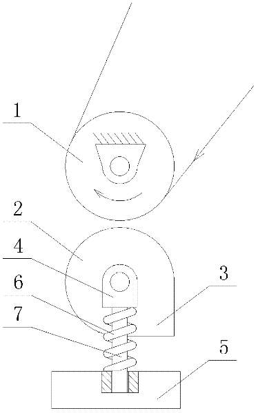
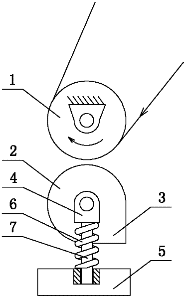
[0010] Such as figure 1 As shown, the magnetic brake device of the present invention includes a belt roller 1 and a brake roller 2, the roller edge of the brake roller 2 has a right-angled brake block 3, and the roller shaft of the brake roller 3 is installed on On the support block 4, the lower rod body 7 of the support block 4 is inserted into the chute of the electromagnetic brake 5, and the electromagnetic brake 5 drives an electromagnetic brake spring 6, and the electromagnetic brake spring 6 is sleeved on the support block 4 Outside the lower rod body 7, and the top end of the electromagnetic brake spring 6 is supported on the brake block 3.

[0011] The magn...


PUM


Abstract

The invention provides a magnetic braking device, which comprises a belt roller and a braking roller, wherein the rolled edge of the braking roller is provided with a right-angle type braking block, the roller shaft of the braking roller is installed on a supporting block, the lower rod body of the supporting block is inserted into a sliding chute of an electromagnetic brake, the electromagnetic brake drives an electromagnetic braking spring, the electromagnetic braking spring is sleeved outside the lower rod body of the supporting block, and the top end of the electromagnetic braking spring is supported on the braking block. The magnetic braking device provided by the invention has the beneficial effects that the electromagnetic braking spring is driven by the electromagnetic brake, and the braking roller is ejected by the supporting block; when the braking roller and the belt roller rotate simultaneously, the right-angle type braking block of the braking roller is contacted with the belt roller, thus the friction force is increased and the braking effect is achieved; and after the electromagnetic braking spring shrinks, the braking roller falls to the sliding chute of the electromagnetic brake along with the electromagnetic braking spring under the action of self gravity.

Description

technical field [0001] The invention relates to a magnetic braking device, which belongs to the field of coating composite equipment. Background technique [0002] Reel materials such as plastic film, paper, and aluminum foil often need to be glued and compounded, and multiple coating and compounding equipment such as compound machines and rewinders are required. The situation requires brakes, so the brake device is an indispensable device on such coating compound equipment. However, the currently commonly used braking device adopts mechanical braking, and the equipment is relatively complicated, and additional equipment actions are required to restore the braking device to its original position after braking, so the equipment is relatively inconvenient to use. Contents of the invention [0003] The technical problem to be solved by the present invention is to overcome the problem that the braking device in the existing coating compound equipment adopts mechanical braking...

Claims


Application Information

Patent Timeline
Patent Type & Authority Applications(China)
IPC IPC(8): F16D49/00
Inventor 吴伟平
Owner WUXI JIANGSU WEIFENG PRINTING MACHINE
Learn More