Multi-rotor aircraft

A multi-rotor aircraft and rotor technology, which is applied in the field of aircraft, can solve the problems of low lift and weight, poor stability and maneuverability, and poor carrying capacity of aircraft, so as to improve the carrying capacity, improve the lift/weight ratio, and increase the stability. Sexual and Manipulative Effects

Inactive Publication Date: 2012-06-20
CHANGCHUN INST OF OPTICS FINE MECHANICS & PHYSICS CHINESE ACAD OF SCI
View PDF0 Cites 8 Cited by
  • Summary
  • Abstract
  • Description
  • Claims
  • Application Information

AI Technical Summary

Problems solved by technology

The common problems of the above-mentioned rotorcraft are: it is a kinematic coupling system itself, the direction and attitude in flight are coupled, the stability and maneuver

Method used


Image

  • Multi-rotor aircraft
  • Multi-rotor aircraft
  • Multi-rotor aircraft

Examples


Embodiment 1

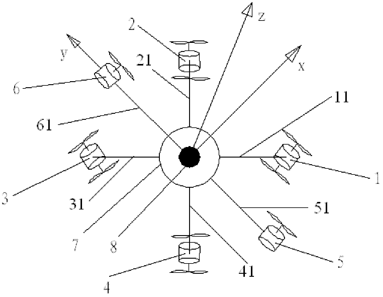
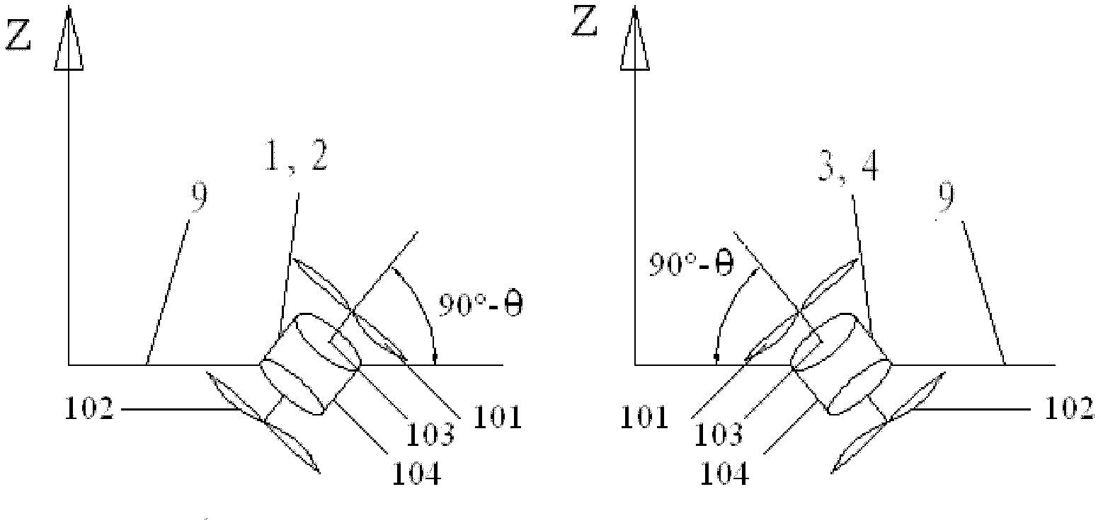
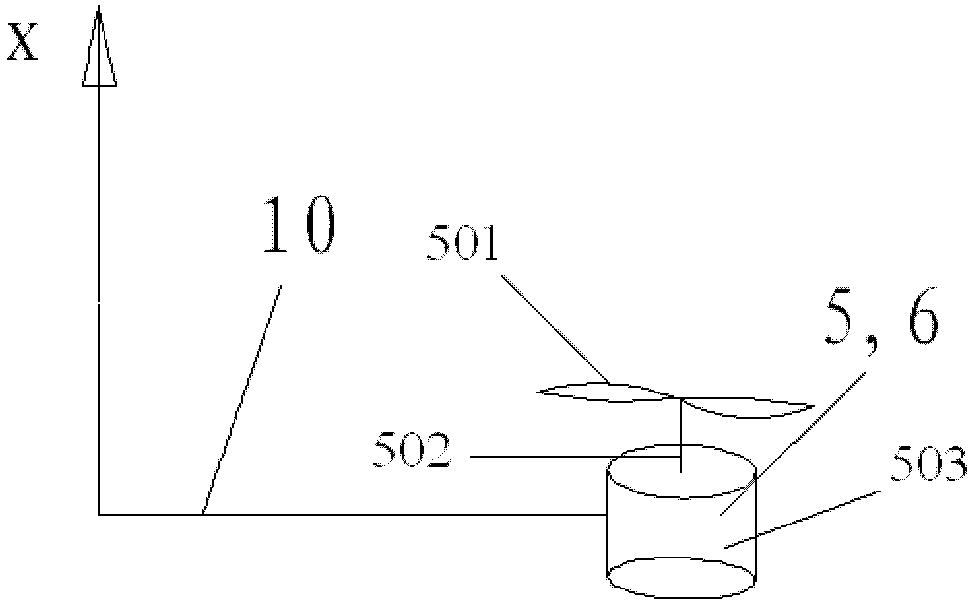
[0038] Such as figure 1 As shown, the present invention includes four main rotor systems 1, 2, 3, 4, two auxiliary rotor systems 5, 6, a body 7, and a flight integrated system 8 installed in the body 7, with six protruding out of the periphery of the body 7. Connecting rods 11, 21, 31, 41, 51, 61, flight integrated system 8 includes control system, inertial sensor and attitude measurement system, navigation system, image acquisition and transmission system, the origin of the aircraft body coordinate system is the center of gravity of the aircraft , The z-axis is vertically upward, the x-axis is perpendicular to the z-axis, pointing forward, the y-axis is determined by the right-hand rule, the aileron systems 5 and 6 are distributed on both sides of the x-axis, and the main rotor systems 1 to 4 are respectively distributed in the body coordinate system Within the four quadrants of the xy plane. The four main rotor systems 1, 2, 3, 4 are equipped with coaxial inverted double roto...

Embodiment 2

[0043] Such as Figure 5 As shown, the main rotor system 111 includes four ducted propeller structures, the aileron system 511 of two ducted propeller structures, the dish-shaped body 711, and the flight integrated system 811 installed in the body 711, the flight integrated system 811 includes Control system, inertial sensor and attitude measurement system, navigation system, image acquisition and transmission system, the origin of the aircraft body coordinate system is the center of gravity of the aircraft, the z-axis is vertically upward, the x-axis is perpendicular to the z-axis, pointing forward, and the y-axis Determined by the right-hand rule, the auxiliary rotor systems 511 are distributed on both sides of the x-axis, and the four main rotor systems 111 are respectively distributed in the four quadrants of the xy plane of the body coordinate system. In the four main rotor systems, each rotation axis of the main rotor systems 1 and 2 forms an angle of 45° clockwise with t...


PUM


Abstract

The invention relates to a multi-rotor aircraft. The multi-rotor aircraft comprises four main rotor systems, two auxiliary rotor systems, an aircraft body and an integrated flight system which is arranged in the aircraft body, wherein an original point of a coordinate system of the aircraft body is the center of gravity of the aircraft, a z axis is vertical upwards, an x axis is vertical to the z axis and points forward, and a y axis is determined by a right-hand rule; the four main rotor systems are respectively distributed in four quadrants of an xy plane of the coordinate system of the aircraft body; an included angle theta is formed between each rotary axis of the four main rotor systems and the z axis of the coordinate system of the aircraft body; and the projection of each rotary axis to an xoy plane of the coordinate system of the aircraft body is coincided with the projection of a connecting line of a rotary center and the original point of the coordinate system of the aircraft body to the xoy plane of the coordinate system of the aircraft body. By regulating the rotary speed of the four main rotor systems and the two auxiliary rotor systems, the movement and attitude of the aircraft can be changed, the aircraft can vertically take off and land, fly forwards, fly backwards, hover and roll, and the multi-rotor aircraft is high in stability and controllability.

Description

Technical field [0001] The invention relates to the field of aircraft, in particular to a multi-rotor aircraft. Background technique [0002] Rotor-type aircraft with vertical take-off and landing and hovering functions not only play an important role in the military field, but also show great application potential in disaster scene rescue, hazardous environment exploration, traffic surveillance, or aerial photography, and have been widely used. attention. [0003] The current rotor type aircraft mainly include four structural forms: single-rotor (main rotor + tail rotor) helicopter, double-rotor (coaxial anti-propeller) helicopter, four-rotor aircraft and six-rotor aircraft, such as McDonnell Douglas MH-16 helicopter , Russia’s Ka-29 helicopter, Germany’s Microdrone company, Canada’s Dranganflyer company’s quadrotor, etc. A single-rotor helicopter or a coaxial anti-propeller helicopter needs a tail rotor to eliminate the torque generated by the rotor on the body. A quadrotor air...

Claims


Application Information

Patent Timeline
IPC IPC(8): B64C27/02B64C27/32
Inventor 白越孙强
Owner CHANGCHUN INST OF OPTICS FINE MECHANICS & PHYSICS CHINESE ACAD OF SCI
Why Eureka
Try Eureka