Shading tool for vehicle driving

A technology of tools and visors, which is applied to vehicle parts, anti-glare equipment, transportation and packaging, etc., can solve the problems of drivers' vision loss, mental stress, and unfavorable safety of passing cars and pedestrians, etc., and achieves wide application, simple structure, Ease of promotion

Inactive Publication Date: 2012-06-20
董建书
View PDF4 Cites 4 Cited by
  • Summary
  • Abstract
  • Description
  • Claims
  • Application Information

AI Technical Summary

Problems solved by technology

[0002] When the car is driving at night, the headlights of the oncoming car emit dazzling glare, causing the driver to lose his eyesight instantly, unable to see the road conditions ahead, the vehicle type and loading situation clearly, and not knowing what obstacles are behind the car, which makes people nervous. The safety of vehicles and pedestrians is very unfavorable, and traffic accidents are prone to occur
At present, vehicles can solve the problem of preventing glare caused by incoming light. The usual methods are as follows: ① Ordinary sun visor, install a sun visor made of opaque material in front of the cab, and adjust it by hand to a position where it can temporarily block strong light. , but this kind of visor needs to be manually adjusted again, and it can only block the sunlight obliquely incident from above, but it cannot effectively block the strong light incident from other angles, causing glare. In addition, motor vehicles without cabs, Two / three-wheel motorcycles and electric vehicles cannot be installed with this kind of sun visor; ②Film is attached to the windshield to reduce light transmittance, but it also hinders the effective observation of non-glare areas while preventing glare; ③Wear sunglasses, and drivers who wear myopia glasses cannot wear sunglasses at the same time, and wearing sunglasses seriously affects the line of sight and hinders the effective observation of non-glare areas, thus causing serious safety hazards

Method used


Image

  • Shading tool for vehicle driving
  • Shading tool for vehicle driving
  • Shading tool for vehicle driving

Examples


Embodiment 1

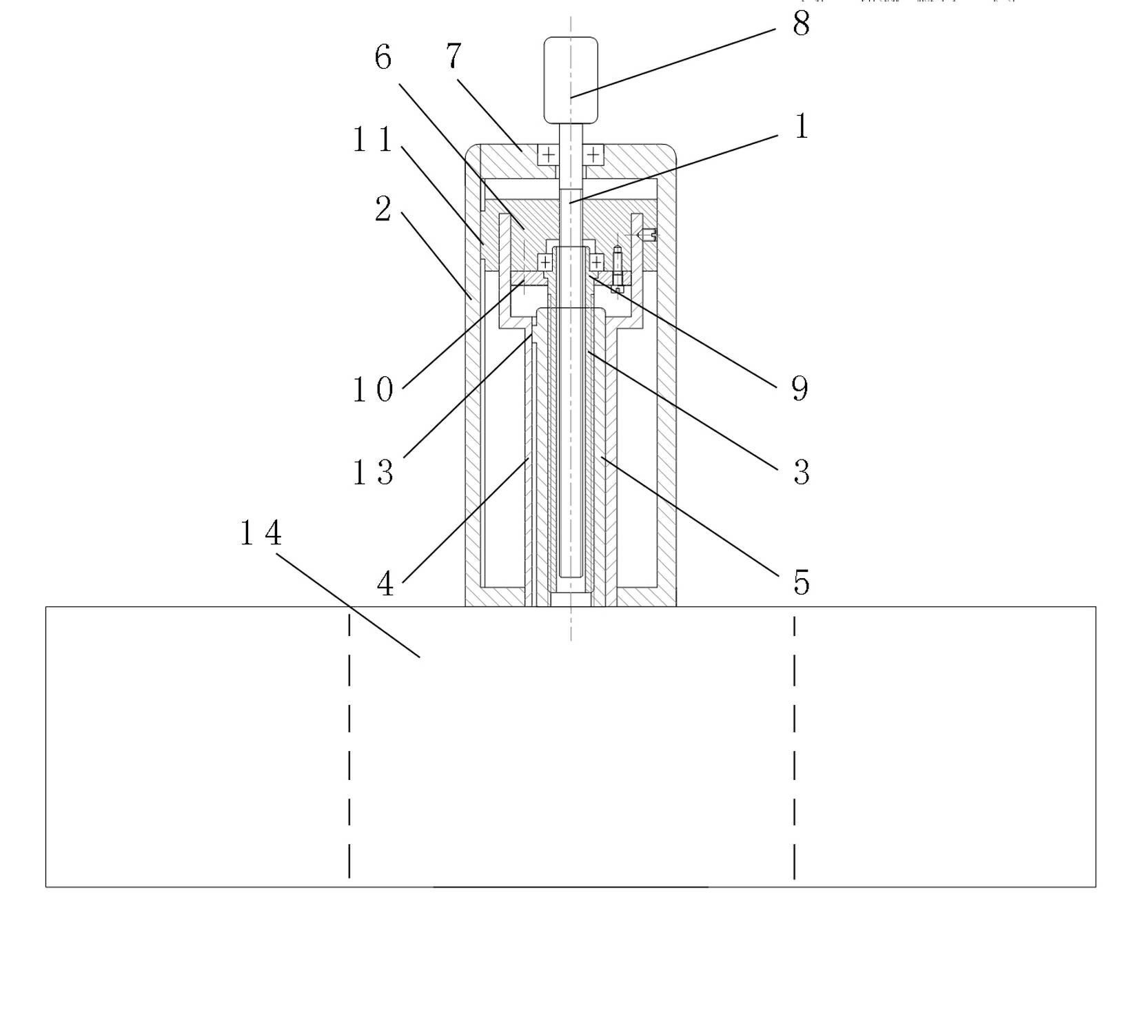
[0027] The motor described in Example 1 is a positive and negative motor, and the electric lifting device adopts a bamboo-type lifting method, taking a three-section spiral synchronous lifting as an example.

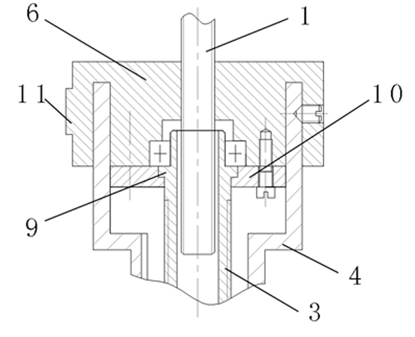
[0028] Such as figure 1 , 2 As shown, the electric lifting device includes a primary active screw 1 and a primary lever body 2 , a secondary lever tray 6 , a secondary active screw 3 , a secondary lever body 4 , and a tertiary lever body 5 . The first-level bar body 2, the second-level bar body 4 and the third-level bar body 5 form a casing sleeve, and the third-level bar body 5 in the innermost layer of the casing pipe is the jacking pipe. The first-level active screw 1 is installed in the first-level lever body 2, the first-level lever body 2 is installed on the base 7, the polished rod part of the first-level active screw 1 is connected with the base 7 through a bearing, and the first-level active screw The power input end 8 of 1 is exposed outside the base 7 and is...

Embodiment 2

[0036] Embodiment 2 adopts the lifting mode step by step step by step. Such as Figure 7 As shown, Embodiment 2 includes a housing 15 , a motor 16 , an electric lifting device and a shade 14 . There is an opening below the housing 15 .

[0037]The electric lifting device includes a multi-segment bushing, and a steel tie bar 17 with a clamping hole, a disc spring 18 and a power input gear 19 installed in the housing 15 . The locking teeth of the power input gear 19 are engaged with the locking holes on the steel stays 17 . The purpose of the disc spring 18 is to tension the steel brace 17 against free expansion. The outermost layer of the multi-section casing is the bottom pipe 20, and the bottom pipe 20 is fixedly installed at the opening below the casing 15. The innermost layer of the casing is the top pipe 21, and the end of the top pipe 21 is fixed with a connection device, the connecting device is connected to the light shielding plate 14 (blocked by the light shieldin...

Embodiment 3

[0041] In addition to the structure in embodiment 1, embodiment 3 also includes a light control switch connected to the motor circuit, and the light control switch includes an external electronic photosensitive head connected to the circuit, a signal conversion circuit, an amplification circuit and a PLC controller . The optical signal collected by the external electronic photosensitive head is converted into an electrical signal by the signal conversion circuit, and then transmitted to the PLC controller set in the circuit after being amplified by the amplifier in the amplification circuit, and the PLC controller controls the motor to rotate forward or reverse. change. The PLC controller of the light control switch under strong light makes the motor rotate forward, and the sun visor 14 is lowered;


PUM


Abstract

The invention discloses a shading tool for vehicle driving. The shading tool comprises a motor, an electric lifting device and a shading plate; the motor drives the electric lifting device; the electric lifting device is connected with the shading plate; the shading tool is characterized in that: the electric lifting device comprises multiple sections of casings which are sleeved into each other; the innermost layer of each casing is provided with a top pipe; and the tail end of each top pipe is connected with the shading plate through a connection device. Compared with the prior art, the shading tool has the characteristics of wide application range, simple structure, low cost and convenience in popularization.

Description

technical field [0001] The invention relates to a vehicle accessory, in particular to a driving shading tool suitable for shading opposite strong light and preventing glare. Background technique [0002] When the car is driving at night, the headlights of the oncoming car emit dazzling glare, causing the driver to lose his eyesight instantly, unable to see the road conditions ahead, the vehicle type and loading situation clearly, and not knowing what obstacles are behind the car, which makes people nervous. The safety of vehicles and pedestrians is very unfavorable, and traffic accidents are prone to occur. At present, vehicles can solve the problem of preventing glare caused by incoming light. The usual methods are as follows: ① Ordinary sun visor, install a sun visor made of opaque material in front of the cab, and adjust it by hand to a position where it can temporarily block strong light. , but this kind of visor needs to be manually adjusted again, and it can only bloc...

Claims


Application Information

Patent Timeline
Patent Type & Authority Applications(China)
IPC IPC(8): B60J3/02
Inventor 董瑞张作状曹卫友张如意崔明湖董建军董建书
Owner 董建书
Why Eureka
Try Eureka