
Cooling jacket for double-wall corrugated pipe

A double-wall corrugated tube and cooling jacket technology, applied in the field of cooling jackets, can solve the problems of increased equipment cost, uneven inner surface quality, uneven cooling, etc., to improve cooling effect and efficiency, ensure product quality uniformity, and achieve good environmental protection. Effects of stiffness and ring compliance

Inactive Publication Date: 2014-05-07
SUZHOU JWELL PRECISION MACHINERY
View PDF6 Cites 0 Cited by
  • Summary
  • Abstract
  • Description
  • Claims
  • Application Information

AI Technical Summary

Problems solved by technology

However, since there is only one coolant inlet, researchers often find that the cooling speed of the inner wall near the coolant inlet is fast, while the cooling speed is slow at the place far away from the coolant inlet. The cooling rate is not uniform, so the ring stiffness and ring compliance of the bellows are poor
[0003]In order to overcome the above-mentioned uneven cooling problem, the traditional technology mainly improves the uniformity problem by increasing the flow rate of cooling water and increasing the effective contact area, but it still exists Disadvantages, the increase of coolant flow rate will cause waste of coolant on the one hand, and on the other hand, with the increase of liquid pressure, it will lead to the need to improve the sealing performance of the system, and the high-demand sealing equipment not only increases the equipment cost but also makes it difficult to realize
Therefore, the traditional cooling method has the disadvantages of poor effect and low efficiency, and the inner surface quality of the product is not uniform, which seriously affects the ring stiffness and ring flexibility of the product.

Method used


Image

  • Cooling jacket for double-wall corrugated pipe
  • Cooling jacket for double-wall corrugated pipe
  • Cooling jacket for double-wall corrugated pipe

Examples


Embodiment Construction

[0020] The advantages of the present invention will become clear and easier to understand by describing the embodiments with the accompanying drawings.

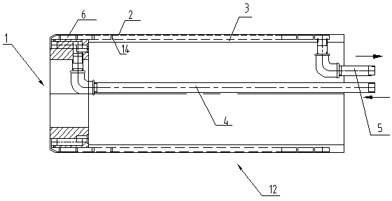
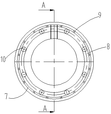
[0021] as attached figure 1 As shown, the cooling jacket of the double-wall corrugated pipe includes a body 12 and a distributor 1 installed at one end of the body 12. The outer jacket 2, the distributor 1 is connected with a coolant inlet pipe 4, and the other end of the body 12 is equipped with a coolant outlet pipe 5, and a cooling cavity for cooling liquid flow is formed between the outer jacket 2 and the inner jacket 3, The liquid outlet pipe 5 communicates with the cooling chamber. The cooling liquid enters the distributor 1 through the liquid inlet pipe 4, and the distributor 1 makes the cooling liquid evenly disperse in the circumferential direction, enters the cooling chamber, and finally flows out through the liquid outlet pipe 5.

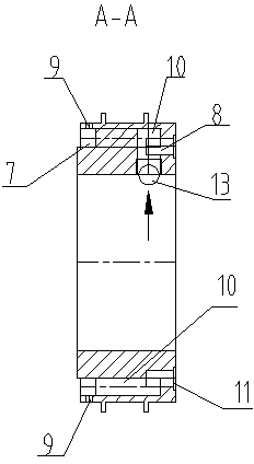
[0022] as attached figure 2 , attached image 3 As shown, a coolant inl...


PUM


Abstract

The invention provides a cooling jacket for a double-wall corrugated pipe. The cooling jacket comprises an inner jacket, an outer jacket coaxially sleeved on the outer side of the inner jacket, a distributor located at one end part of the inner jacket, a cooling liquid inlet pipe mounted on the distributor, and a cooling liquid outlet pipe mounted at the other end part of the inner jacket. A cooling cavity for a cooling liquid to flow is formed between the outer jacket and the inner jacket. A first annular groove and a second annular groove are arranged along the circumference of the distributor. The first annular groove is communicated with the cooling liquid inlet pipe. The distributor is further provided with a plurality of primary liquid outlets which are communicated with the first annular groove and the second annular groove, and with a plurality of secondary liquid outlets which are communicated with the second annular groove and the cooling cavity. The primary liquid outlets and the secondary liquid outlets are separately and uniformly distributed on the distributor along the circumference of the distributor.

Description

technical field [0001] The invention relates to a cooling jacket of a double-wall corrugated pipe, which is used for cooling the inner wall of the corrugated pipe during the forming process of the double-wall corrugated pipe. Background technique [0002] During the production process of the double-wall corrugated pipe, the shape of the outer wall is determined by the crest shape and distribution position of the inner wall of the forming module. The inner surface of the inner wall is formed on the outer surface of the cooling jacket, and the outer surface of the inner wall is extruded and bonded with the trough of the inner surface of the outer wall of the forming module to form the inner and outer walls of the double-wall bellows. The existing inner wall cooling method is to adopt a simple water cooling method for cooling, wherein the water cooling jacket usually includes an outer jacket and an inner jacket, an annular water cooling chamber is formed between the inner jacke...

Claims


Application Information

Patent Timeline
Patent Type & Authority Patents(China)
IPC IPC(8): B29C35/16
Inventor 何海潮王淳德
Owner SUZHOU JWELL PRECISION MACHINERY
Learn More