
Anti-noise wide-range frequency measurement method and phase locking frequency meter

A frequency measurement, anti-noise technology, applied in the direction of frequency measurement devices, etc., can solve the problems of narrow measurable frequency range, unsuitable for wide-frequency range periodic signal measurement, etc., to achieve the effect of strong anti-noise ability and wide measurement frequency range

Active Publication Date: 2012-06-13
INST OF PHYSICS - CHINESE ACAD OF SCI
View PDF6 Cites 14 Cited by
  • Summary
  • Abstract
  • Description
  • Claims
  • Application Information

AI Technical Summary

Problems solved by technology

However, due to the inherent frequency limitation of the phase-locked loop, the measurable frequency range is very narrow, so this technique is not suitable for the measurement of periodic signals in a wide frequency range

Method used


Image

  • Anti-noise wide-range frequency measurement method and phase locking frequency meter
  • Anti-noise wide-range frequency measurement method and phase locking frequency meter
  • Anti-noise wide-range frequency measurement method and phase locking frequency meter

Examples


example 1

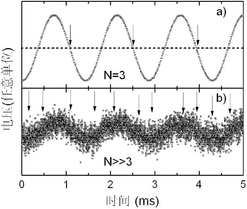
[0071] Figure 5 A schematic diagram showing a specific measurement example of an embodiment of the present invention. Among them, part b) shows the sinusoidal original measured signal with a frequency of 7MHz and a signal-to-noise ratio of -20dB with hollow square dots; part a) shows a sinusoidal reference signal with the same mode as the measured signal. Use the aforementioned anti-noise broadband digital phase-locked frequency meter to measure, use sine wave as reference signal during the measurement process, the measurement results are as follows Figure 6 As shown, the figure shows the variation curve of the correlation degree expressed by the signal amplitude strength with the frequency shift. It is easy to see that the measured frequency, phase and amplitude of the measured signal are 7MHz, 150 degrees and 3mV respectively. image 3 Part b) shows the sinusoidal signal simulated according to the frequency, phase and amplitude of the measurement results with a solid lin...

example 2

[0073] Figure 7 A schematic diagram showing another specific measurement example of an embodiment of the present invention. Part b) shows the original triangular wave signal under test with a frequency of 3Hz, a signal-to-noise ratio of -20dB, and a rise-fall time ratio of 30% with hollow square dots, and part a) shows the same triangular wave pattern as the signal under test reference signal. Use the aforementioned anti-noise broadband digital phase-locked frequency meter for measurement. During the measurement process, a triangle wave signal with a rise-to-fall time ratio of 30% is used as a reference signal. The measurement results are as follows Figure 8 As shown, the figure shows the variation curve of the correlation degree expressed by the signal amplitude strength with the frequency shift. It is easy to see that the measured frequency, phase and amplitude of the measured signal are 3Hz, 159 degrees and 167mV respectively. Figure 5 Part b) shows the simulated tria...


PUM


Abstract

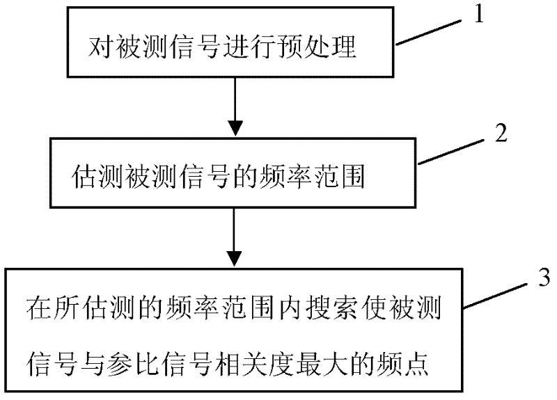
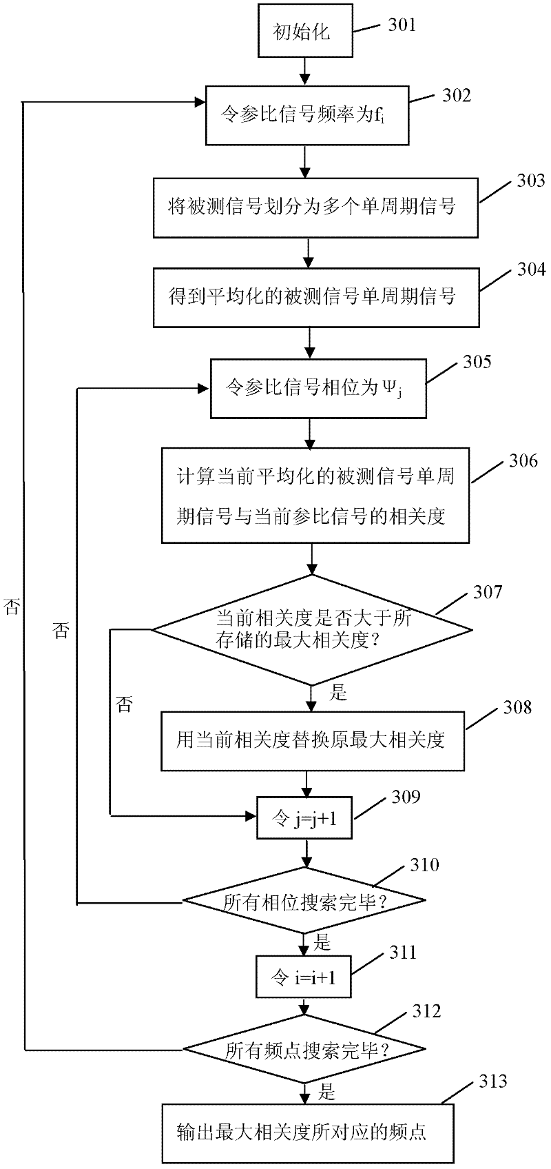
The invention provides an anti-noise wide-range frequency measurement method, which comprises 1 estimating frequency range of measured signals which are digital signals; 2 receiving the measured signals, within the estimated frequency range, sequentially changing frequency values, searching the frequency value which enables degree of correlation of reference signals and the measured signals to be maximum, and taking the frequency value as the frequency value of the measured signals. Signal pattern of the reference signals is the same as that of the measured signals. The invention further provides a corresponding anti-noise wide-range frequency meter, which has strong anti-noise capability, and is capable of accurately measuring signals with low signal to noise ratio and wide in measurable frequency range. In addition, apart from being capable of measuring frequency of signals, the anti-noise wide-range frequency meter is also capable of measuring phase and amplitude of signals synchronously.

Description

technical field [0001] The invention relates to the technical field of electronics and time-frequency measurement, in particular, the invention relates to an anti-noise broadband frequency measurement method and a phase-locked frequency meter. Background technique [0002] At present, there are three basic principles of popular frequency meters in domestic and foreign markets: i) judge the signal period by the interval of rising edge or falling edge and calculate the frequency of the signal under test (refer to Chinese patent CN1056582A); Perform Fourier transform to measure the frequency of the periodic signal; iii) use a phase-locked loop circuit to identify narrowband frequencies (refer to European Patent EP 0430605B1). Among them, the technique of type i) has a good measurement effect for signals with a high signal-to-noise ratio, but when the signal-to-noise ratio of the measured signal is low, the accuracy of this type of measurement scheme will be significantly reduce...

Claims


Application Information

Patent Timeline
IPC IPC(8): G01R23/02
Inventor 陆俊沈保根邵晓萍
Owner INST OF PHYSICS - CHINESE ACAD OF SCI
Learn More