Backlight module and liquid crystal display

A liquid crystal display and backlight module technology, which is applied in the direction of instruments, optics, light guides, etc., can solve the problems of smaller light mixing distance and lower light coupling efficiency, and achieve the effect of ensuring coupling efficiency and picture display quality

Active Publication Date: 2012-06-13
TCL CHINA STAR OPTOELECTRONICS TECH CO LTD
View PDF4 Cites 4 Cited by
  • Summary
  • Abstract
  • Description
  • Claims
  • Application Information

AI Technical Summary

Problems solved by technology

Although the path of the light in the direction B1 perpendicular to the light guide plate 12 becomes longer, the light mixing distance will be reduced to D2, where D2Figure 2B , Figure 2B for Figure 2A In the side view, the light emitted from the LED11 cannot completely enter the light guide plate 12, so that the coupling efficiency of the light in the direction B1 perpendicular to the light guide plate 12 decreases

Method used


Image

  • Backlight module and liquid crystal display
  • Backlight module and liquid crystal display
  • Backlight module and liquid crystal display

Examples


Embodiment Construction

[0028] The following descriptions of the various embodiments refer to the accompanying drawings to illustrate specific embodiments in which the present invention can be practiced.

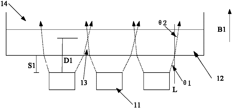
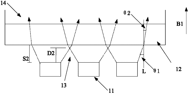
[0029] image 3 It is a structural diagram of a preferred embodiment of the backlight module in the present invention.

[0030] The backlight module includes a light source 31 and a light guide plate 32 , the light guide plate 32 includes a light incident side 321 , and a light redirecting layer is disposed on the light incident side 321 . Wherein, the light redirecting layer is used to change the direction of the light entering the light incident side, so as to shorten the intersection point of the light emitted by the adjacent light source 31 and the light source 31 in the direction B1 perpendicular to the light incident side 321 distance.

[0031] Wherein, the shortening referred to in this embodiment refers to the distance of the intersection point of the light emitted by adjacent light sourc...


PUM

PropertyMeasurementUnit
refractive indexaaaaaaaaaa

Abstract

The invention discloses a backlight module comprising light sources and a light guide plate, wherein the light guide plate comprises a light incident side; rays emitted by the light sources enter into the light guide plate through the light incident side; the light incident side is provided with a ray steering layer; and the tray steering layer is used for changing the direction of rays entering into the light incident side so as to shorten the distance from a cross point of rays emitted by two adjacent light sources to the light sources in the direction vertical to the light incident side. The invention also discloses a liquid crystal display.

Description

【Technical field】 [0001] The invention relates to the technical field of liquid crystal production, in particular to a backlight module and a liquid crystal display. 【Background technique】 [0002] With the continuous popularization of liquid crystal displays, the requirements for liquid crystal display functions are getting higher and higher. [0003] Figures 1A-1B It is a partial structural diagram of a backlight module in the prior art. see Figure 1A , Figure 1A It is a cross-sectional view of the backlight module. When setting up the light emitting diode (Light Emitting Diode, LED) 11 and the light guide plate 12, the coupling efficiency of the light emitted by the LED 11 must be considered, including the distance between the LED 11 and the light guide plate (LGP) 12. The coupling efficiency of light between. See for example Figure 1B , Figure 1B for Figure 1A In the side view, when the distance between the LED 11 and the light guide plate 12 is S1, all the ...

Claims


Application Information

Patent Timeline
Patent Type & Authority Applications(China)
IPC IPC(8): F21S8/00F21V8/00G02F1/13357
CPCG02B6/0068G02F1/1335G02B6/0023G02B6/00F21V17/00
Inventor 康志聪
Owner TCL CHINA STAR OPTOELECTRONICS TECH CO LTD
Why Eureka
Try Eureka