Anti-deforming structure of cam plate

A technology of deformation structure and cam disc, which is applied in the field of mechanical parts, can solve the problem of large operating force of the controller, and achieve the effect of preventing warping and deformation

Inactive Publication Date: 2012-06-13
CHENGDU AEROSPACE MOLD & PLASTIC CO LTD
View PDF0 Cites 0 Cited by
  • Summary
  • Abstract
  • Description
  • Claims
  • Application Information

AI Technical Summary

Problems solved by technology

[0003] The technical problem to be solved by the present invention is to provide an anti-deformation structure for the cam disc, which can effectively prevent the warping deformation of the cam disc body and improve the deformation caused by the warping of the cam disc body. The bending deformation directly causes the motion mechanism to fail to run according to the set track, which leads to the defect that the operating force of the controller and the like is too large during the operation process.

Method used


Image

  • Anti-deforming structure of cam plate
  • Anti-deforming structure of cam plate
  • Anti-deforming structure of cam plate

Examples


Embodiment Construction

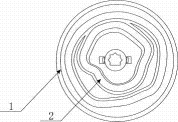
[0012] The specific embodiment of the present invention is described in detail below in conjunction with accompanying drawing:

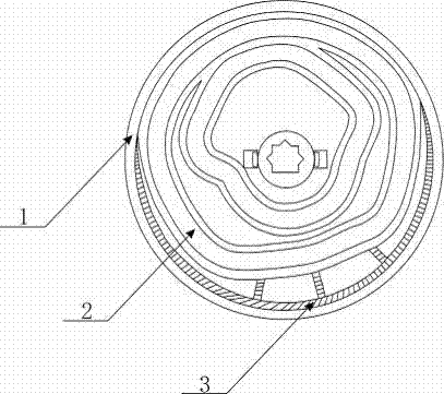
[0013] As shown in the figure, the anti-deformation structure of the cam disc includes a track groove 2 and a cam disc body 1; the cam disc body 1 and the track groove 2 are arranged as a whole; it is characterized in that: 1 The joint is also provided with reinforcing ribs 3.

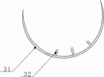
[0014] The reinforcing rib 3 is arranged on the outermost side of the connection between the cam plate body 1 and the track groove 2 . A rib body 31 and ribs 32 connected with the rib body 31 are arranged on the reinforcing rib 3, and there are at least three ribs 32. The ribs are provided to prevent warping of the cam disc body.

[0015] To sum up, using the anti-deformation structure of the cam provided by the utility model can effectively prevent the warping deformation of the cam disc body, and improve the movement mechanism that cannot run according to the set track dir...


PUM


Abstract

This invention discloses an anti-deforming structure of a cam plate, which comprises a track groove and a cam plate body, wherein the cam plate body is integrated in the track groove; a connecting position of the track groove and the cam plate body is also provided with a reinforcement rib; the anti-deforming structure disclosed by this utility model can effectively prevent the cam plate body from being wrapped or deformed and improve a disadvantage that a movement mechanism cannot be operated according to a defined track because of a wrapped or deformed cam plate body so as to cause overlarge operation force in an operating procedure of a controller and the like.

Description

technical field [0001] The invention relates to the technical field of mechanical parts, in particular to a cam disc anti-deformation structure. Background technique [0002] Such as figure 1 As shown, the track groove 2 and the cam disc body 1 are a whole (that is, a part), drive the control rod or connecting rod along the cam track groove, and then drive the rotation of each damper, so as to realize the opening and closing control of the damper and achieve the damper Open and close controls according to the set mode. Because the track groove 2 has to meet the requirements of the movement design of the mechanism, the distribution of the track groove 2 on the front and back of the cam plate body 1 is unbalanced (that is, the local wall thickness distribution of the product parts is uneven, resulting in uneven stress distribution of the product during injection molding. Uniform, resulting in a large amount of local deformation of the product). The warping deformation of th...

Claims


Application Information

Patent Timeline
Patent Type & Authority Applications(China)
IPC IPC(8): F16K31/524
Inventor 杨世海蔡淑琼徐静
Owner CHENGDU AEROSPACE MOLD & PLASTIC CO LTD
Why Eureka
Try Eureka