
Power control system and control method for engineering machinery

A technology of power control system and construction machinery, applied in fluid pressure actuating system components, mechanical equipment, fluid pressure actuating devices, etc., can solve the problem of affecting the response speed of the system, the operating cost is not effectively controlled, and the engine speed is slow to increase, etc. problems, to achieve the best economic results

Inactive Publication Date: 2012-06-13
SANY HEAVY IND CO LTD (CN)
View PDF6 Cites 17 Cited by
  • Summary
  • Abstract
  • Description
  • Claims
  • Application Information

AI Technical Summary

Problems solved by technology

[0004] However, the power of the engine is jointly determined by the engine speed and output torque. After determining the engine power suitable for the working conditions, no effective measures have been taken to adjust the engine speed and torque.
Since the engine fuel consumption is determined by the engine speed and engine torque, if the engine speed and torque are not properly adjusted, the engine fuel consumption cannot be reasonably controlled, and the operating cost cannot be effectively controlled
Moreover, even if the engine oil consumption is controlled, the energy consumption of the power system of the entire construction machinery may be high and the engine utilization rate may be low
[0005] In addition, the supercharging system of the engine power system is usually a turbocharging system. When the engine speed is increased from a low speed to a high operating speed, due to the lag of the turbocharger, the engine speed increases slowly, which affects the system response speed.

Method used


Image

  • Power control system and control method for engineering machinery
  • Power control system and control method for engineering machinery
  • Power control system and control method for engineering machinery

Examples


specific Embodiment approach

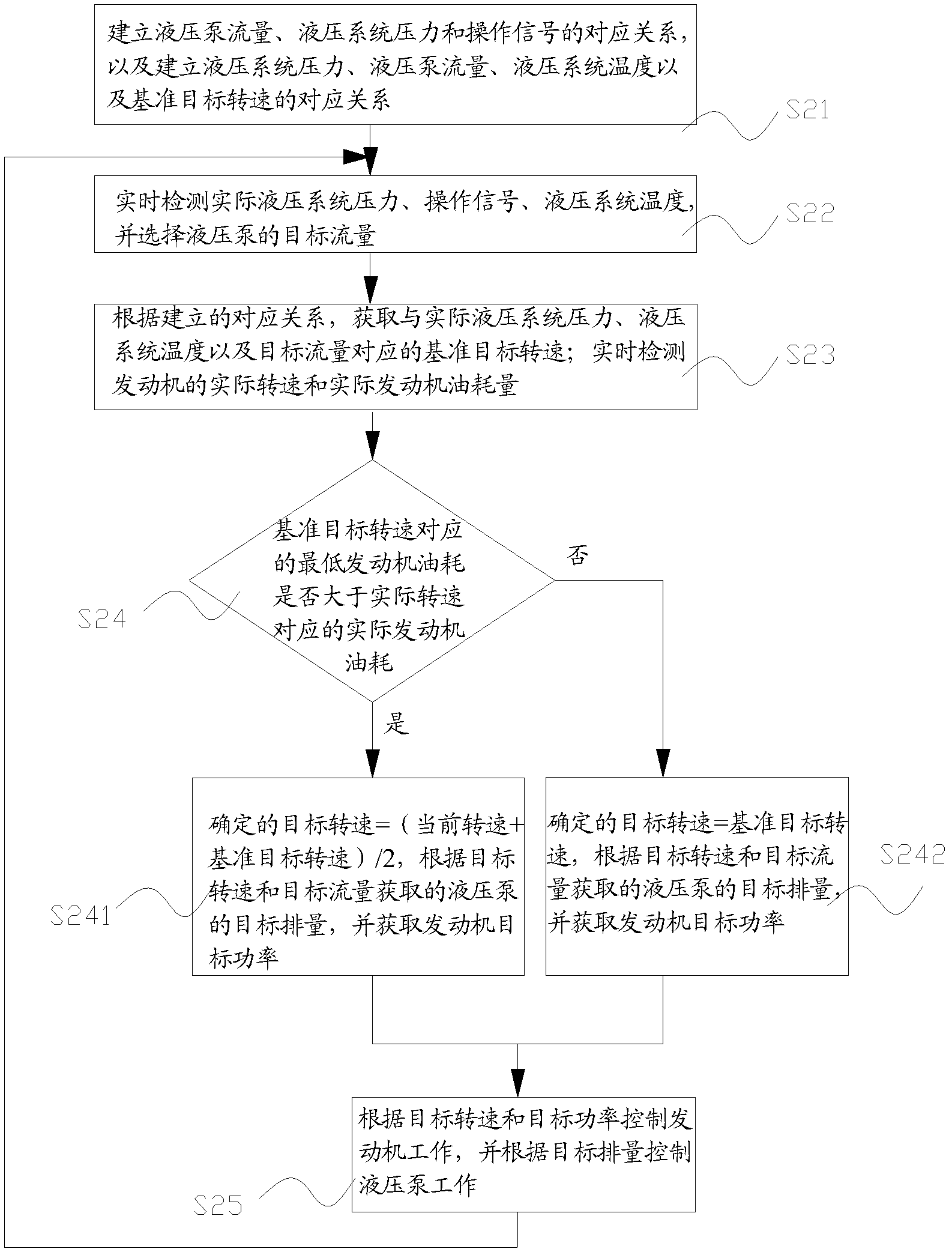
[0090] This embodiment comprises the following steps:

[0091] S21) Establishing the corresponding relationship between hydraulic pump flow, hydraulic system pressure and operation signal, and establishing the corresponding relationship between hydraulic system pressure, hydraulic pump flow, hydraulic system temperature and reference target speed;

[0092] In this specific implementation manner, further improvements are made to the first embodiment. Since the temperature of the hydraulic system has an impact on the efficiency of the hydraulic pump, when calculating the benchmark target speed according to the functional relationship between the engine speed and the system energy consumption, the influence of temperature on the system energy consumption can also be considered, that is, the system energy consumption η(n, v, T) =b(n, T) / ηb(p, n, v, t'), where t' is the temperature of the hydraulic system.

[0093] When the pressure of the hydraulic system, the flow rate of the hy...


PUM


Abstract

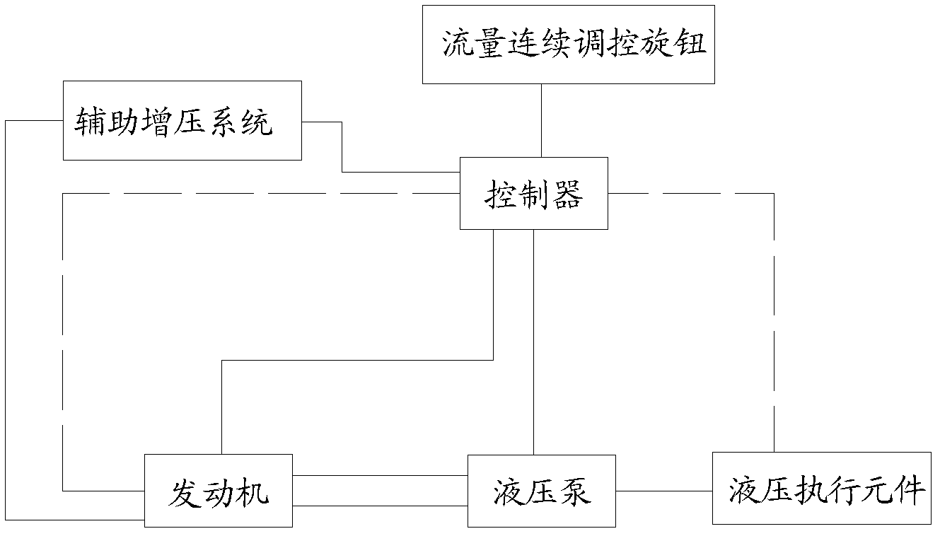
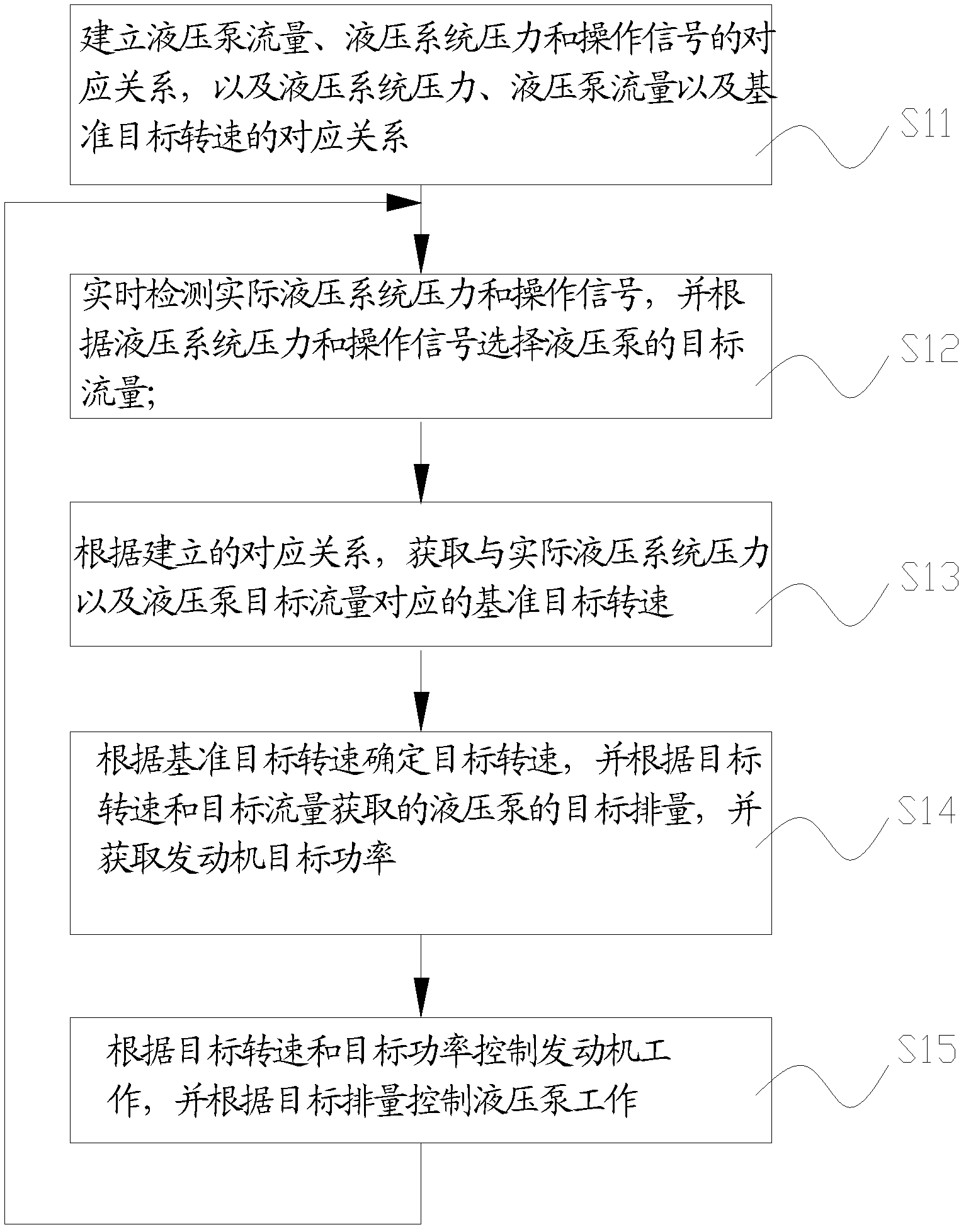
The invention discloses a power control system and control method for the engineering machinery. The control method comprises the following steps: 10) prestoring the corresponding relationship of hydraulic pump flow, the hydraulic system pressure and the operation signal, and building the corresponding relationship of hydraulic system pressure, hydraulic pump flow and reference target revolving speed; 20) obtaining a practical hydraulic system pressure and operation signal, and selecting a hydraulic pump and target flow; 30) obtaining the reference target revolving speed corresponding to the practical hydraulic system pressure and the target flow; 40) determining the target revolving speed, the target displacement and the engine target power; and 50) controlling the engine to work according to the target revolving speed and the target power, and ensuring that the hydraulic pump works according to the target flow. With the method, the whole power system fuel economy and efficiency can be comprehensively considered. Under the condition of satisfying the load requirement, engine fuel consumption amount and hydraulic pump efficiency are used for comprehensively calculating to find the target revolving speed with the optimal economy. The invention also discloses a power control system for the engineering machinery.

Description

technical field [0001] The invention relates to the technical field of construction machinery, in particular to a power control system and a control method of construction machinery. Background technique [0002] The power system of construction machinery usually includes a hydraulic system and an engine. The engine drives the hydraulic pump of the hydraulic system, and the hydraulic pump drives the hydraulic actuator. The flow rate of the hydraulic pump in the hydraulic system determines the action speed of the actuator. Taking an excavator as an example, during operation, the flow rate of the hydraulic pump in the hydraulic system determines the speed of excavation. The flow rate of the hydraulic system is usually controlled by the operator according to the actual working conditions or actual operating efficiency requirements. The flow rate of the hydraulic pump is the product of the displacement and the rotational speed of the hydraulic pump, and the rotational speed of t...

Claims


Application Information

Patent Timeline
IPC IPC(8): F15B21/08F15B15/18
Inventor 孙普阎智慧
Owner SANY HEAVY IND CO LTD (CN)
Learn More