Ballasting method in large-span girder cantilever construction

A mid-construction, long-span technology, applied to bridges, bridge construction, erection/assembly of bridges, etc., to achieve the effect of saving materials and not occupying the operating space of steel beams

Active Publication Date: 2014-01-15
CHINA RAILWAY MAJOR BRIDGE ENG GRP CO LTD
View PDF5 Cites 0 Cited by
  • Summary
  • Abstract
  • Description
  • Claims
  • Application Information

AI Technical Summary

Problems solved by technology

[0008] The technical problem to be solved by the present invention is to solve the problem that there are certain limitations in the cantilever construction of large-span steel beams in terms of physical weight and post-anchoring

Method used


Image

  • Ballasting method in large-span girder cantilever construction
  • Ballasting method in large-span girder cantilever construction
  • Ballasting method in large-span girder cantilever construction

Examples


Embodiment Construction

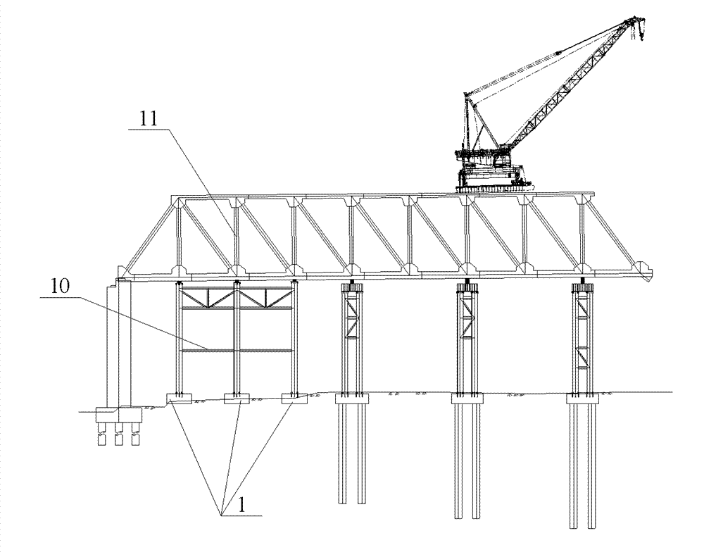
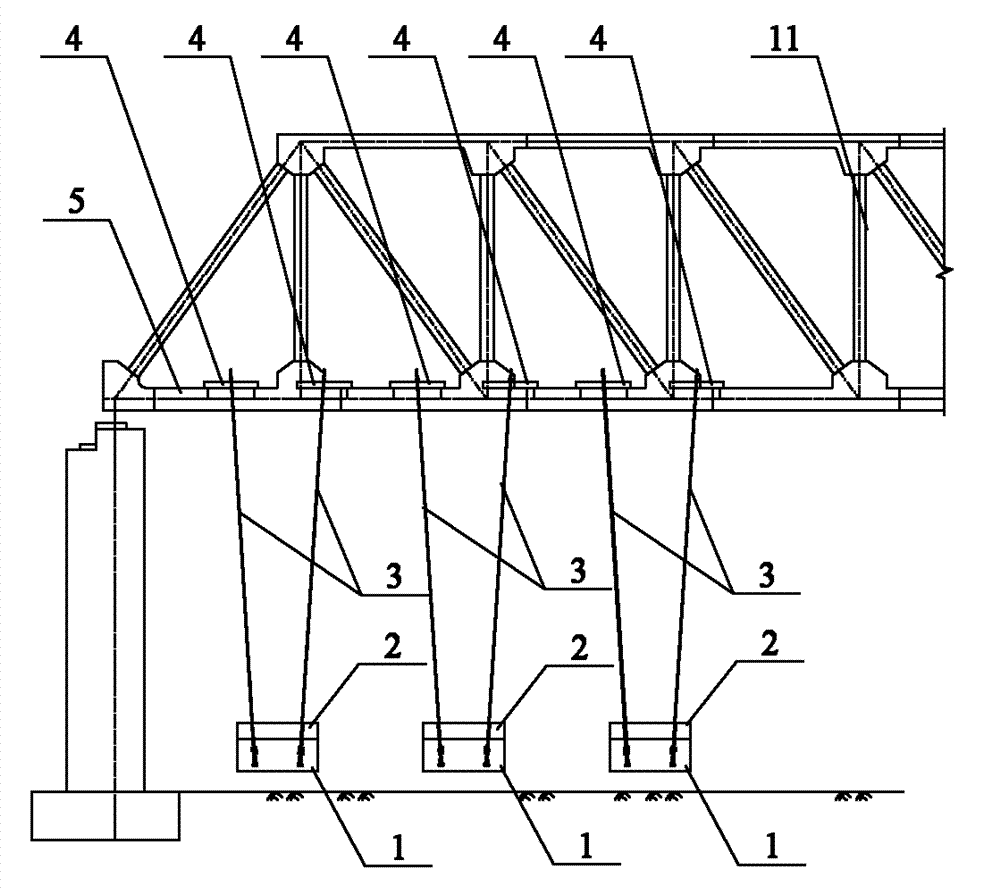
[0022] The invention provides a ballast method in the cantilever construction of a large-span steel beam, using the enlarged concrete foundation of the temporary pier of the side-span steel beam as the ballast material, that is, after the construction of the side-span steel beam is completed, the temporary pier is removed, The expanded concrete foundation of the side-span steel girder temporary buttress is connected to the steel girder bridge deck with steel strands, and the concrete enlarged foundation of the side-span steel girder temporary buttress is lifted through the steel strands to form a cross-span steel girder Heavy.

[0023] The present invention will be described in detail below in conjunction with the accompanying drawings.

[0024] The ballast method in the large-span steel girder cantilever construction provided by the invention, concrete steps are as follows:

[0025] A10, such as figure 1 As shown, first construct the expanded foundation 1 of the side-span s...


PUM


Abstract

The invention discloses a ballasting method in large-span girder cantilever construction. The ballasting method comprises the following steps of: A10, constructing an enlarged foundation of temporary piers for a side span girder, and arranging an embedded steel strand; A20, constructing the temporary piers on the enlarge foundation; A30, detaching the temporary piers after the side span girder is erected; A40, mounting distributive girders on a bridge deck of the side span girder, and making a steel strand pass through drain holes on the bridge deck of the side span girder and fixedly connected with the embedded steel strand; A50, when the factor of safety against overturning of the girder cantilever is less than 1.3, beginning ballasting, tensioning the steel strand by using a tensioning jack arranged on the bridge deck of the side span girder, lifting the enlarged foundation, and anchoring the upper end of the steel strand to the distributive girders to ballast the side span girder; and A60, after a girder is folded, descending the enlarged foundation by using the tensioning jack and the steel strand to unload the ballast. By the method, the enlarged foundation is integrated with a ballasting material, and the method has the advantages of saving materials, not occupying girder operating space, not influencing the jacking and drop and longitudinal shift of the girder, and the like.

Description

technical field [0001] The invention relates to a bridge construction method, in particular to a weight method in the cantilever construction of a large-span steel girder. Background technique [0002] During the steel beam construction process, the side spans are generally erected with temporary support piers to assist the cantilever erection. After the side span steel beam cantilever is erected to the main pier, the full cantilever erection is carried out. Finally, the middle span is closed by jacking down and longitudinally moving the steel beam. When the cantilever length of the steel girder is large, it is necessary to press on the side span to meet the requirement of anti-overturning stability safety factor K≧1.3. [0003] There are two traditional weighting methods: [0004] (1) Physical weight. Water tanks or concrete, steel and other objects are used for ballasting on the bridge deck or on the top chord of the steel girder. The advantage of this method is that the...

Claims


Application Information

Patent Timeline
Patent Type & Authority Patents(China)
IPC IPC(8): E01D21/10
Inventor 覃勇刚邓敬雄汪芳进李军堂涂满明王东辉宋小三张爱花陈国祥钱洪燕王殿伟徐启利彭梦泽胡雄伟
Owner CHINA RAILWAY MAJOR BRIDGE ENG GRP CO LTD
Why Eureka
Try Eureka