
Blade for silk-screen printing on a substrate

A technology of screen printing and blade, applied in the direction of screen printing machine, printing, printing machine, etc., can solve problems such as inability to guarantee, and achieve the effect of avoiding disturbance phenomenon

Inactive Publication Date: 2012-05-30
APPLIED MATERIALS INC
View PDF8 Cites 5 Cited by
  • Summary
  • Abstract
  • Description
  • Claims
  • Application Information

AI Technical Summary

Problems solved by technology

[0009] However, the known linear motors described above suffer from switching disturbances and consequent control problems when the coil moves from a position facing the positive magnet to a position facing the negative magnet (or vice versa)
[0010] As a result, these control difficulties often fail to guarantee the characteristics of resolution, accuracy, pressure control, and printing conditions that are simultaneously required when performing screen printing, especially for silicon wafer screen printing for photovoltaic cells

Method used


Image

  • Blade for silk-screen printing on a substrate
  • Blade for silk-screen printing on a substrate
  • Blade for silk-screen printing on a substrate

Examples


Embodiment Construction

[0048] Referring to the drawings, a blade 10 according to the invention is used in a suitable printing head for screen printing a printing material (in this case a printing paste for screen printing, such as a conductive paste, but not only limited to this) to replicate desired circuits on the substrate, such as conductive circuits, in this example, planar components such as electronic or similar devices are placed below the grid, and these planar components are used, for example, to manufacture Silicon-based wafers for photovoltaic cells.

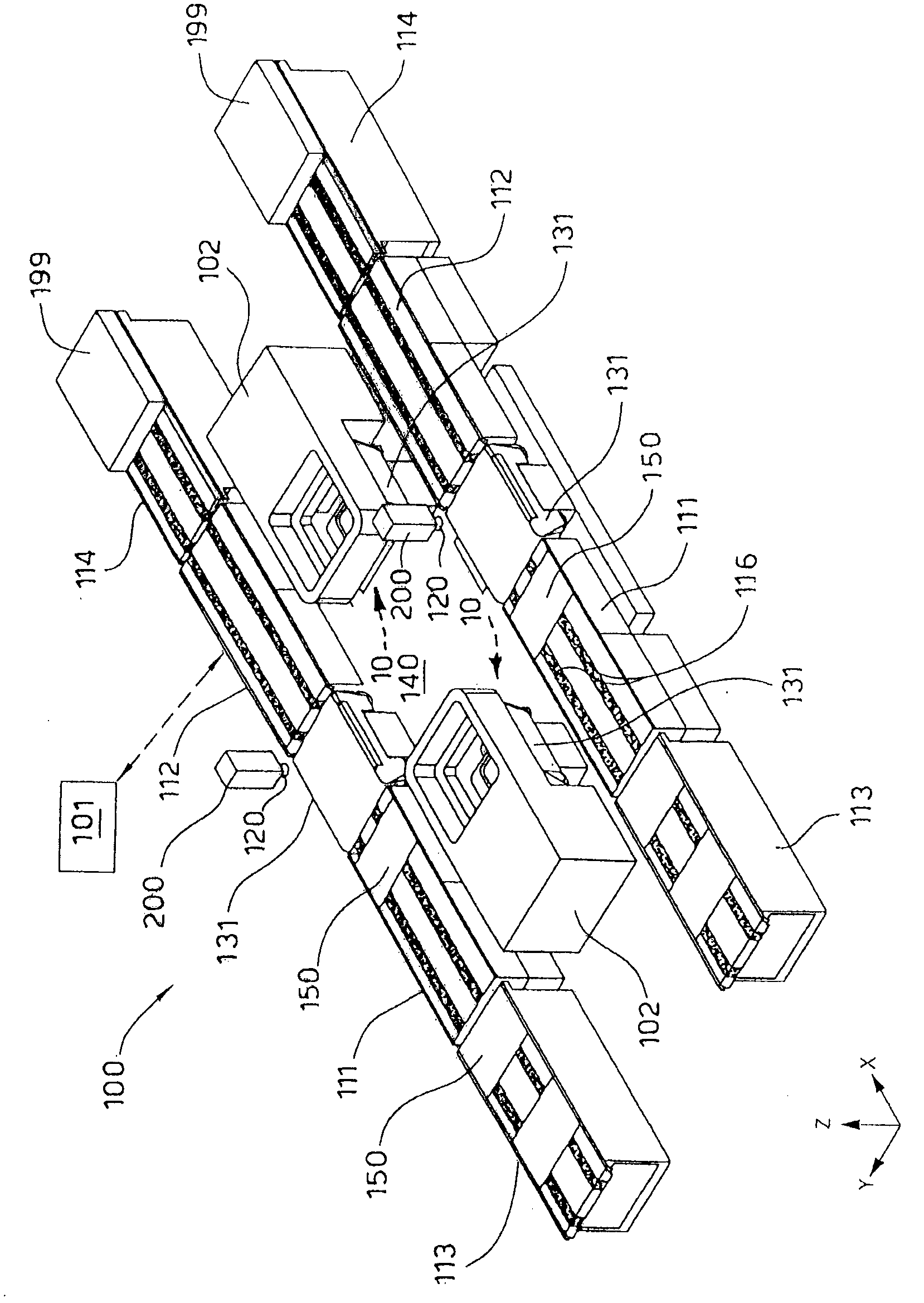
[0049] figure 1 An isometric view of a substrate screen printing processing system or system 100 with screen printing components designed to screen print a patterned layer of material on a substrate 150 . In particular, the system 100 provides a plurality of print heads 102 each having a blade 10 according to the present invention. In one embodiment, the system 100 generally includes two incoming conveyors 111, an actuator assembly 140, a ...


PUM


Abstract

Blade (10) for the silk-screen printing of one or more print tracks on substrates (150) by means of a print material deposited on a print substrate (150) by means of a silk-screen printing net (50). The blade (10) comprises a print extremity (18) and a supporting structure able to support the print extremity (18). The supporting structure comprises a support frame (12) fixed to a slider (14) mobile with respect to the support frame (12), which slider positions the print extremity (18) at least with respect to the net (50) below. Actuation members are provided to determine the movement of the slider (14) with respect to the support frame (12). The actuation members comprise a linear actuator of the voice coil type.

Description

technical field [0001] The present invention relates to a blade for screen printing one or more printed circuits on a substrate, such as a flat panel assembly of an electronic device or other similar assembly containing silicon (such as a wafer, substrate or sheet) A plurality of conductive printed lines are screen printed on to fabricate photovoltaic cells. It is not excluded, however, that other specific substrates or printing support plates may be provided in other fields where printing operations are used. Background technique [0002] It is well known that the technique for fabricating conductive lines on silicon-based wafers (especially for, but not limited to, photovoltaic cells) is screen printing using suitable printing materials, such as conductive paste or ink, and appropriate A screen-printed grid is used, and a layer of emulsion is coated on the surface of the grid, and the emulsion layer is properly cut according to the expected laying pattern of the circuit t...

Claims


Application Information

Patent Timeline
Patent Type & Authority Applications(China)
IPC IPC(8): B41F15/42B41F15/44H02K41/035
CPCH02K41/0356H05K2203/0139B41F15/44H05K3/1233
Inventor 詹佛朗哥·帕斯奎林安德里亚·巴奇尼乔治欧·塞勒里卢奇·德萨缇马科·加里亚左托马索·沃尔克斯
Owner APPLIED MATERIALS INC
Learn More