Manual tripping device of marine motor brake

A manual release and marine motor technology, applied in the direction of brake actuators, mechanical equipment, gear transmission mechanisms, etc., can solve the problems of not meeting the protection level, many operating actions, and no sealing structure, etc., to achieve simple structure, low cost, Create easy effects

Inactive Publication Date: 2012-05-30
TAIZHOU CITY YUANDA ELECTRIC MOTOR MFG
View PDF0 Cites 0 Cited by
  • Summary
  • Abstract
  • Description
  • Claims
  • Application Information

AI Technical Summary

Problems solved by technology

There are two types of manual release mechanisms in the prior art: external and built-in. The external structure is fixed on the brake housing, which is a crank fork structure. The operating handle is outside the brake housing, and the mechanism extends from the brake housing hole into the inside of the brake to move. The position of the armature is to realize manual release. This structure can realize manual release, but the structure is more complicated, and there is no sealing structure, which cannot meet the requirements of marine motors with high protection level requirements; When the driven translation mechanism needs to be released manually, first remove the blocking cover on the brake housing, and extend the special wrench into the brake housing to adjust the adjusting screw to realize manual release; after manual release, seal the blocking cover
This kind of built-in structure is simple and can realize manual release, but there are many operation actions, and manual release cannot be realized quickly

Method used


Image

  • Manual tripping device of marine motor brake
  • Manual tripping device of marine motor brake

Examples


Embodiment Construction

[0014] The present invention will be further described below according to the accompanying drawings and in conjunction with the embodiments.

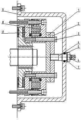
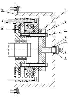
[0015] The marine motor brake manual release device shown in the accompanying drawings is a screw-driven lever translation mechanism consisting of a screw mechanism and a translation mechanism; the translation mechanism includes a support plate 1, an adjustment plate 2, a connecting bolt 3 and an armature 1.3, two The connecting bolts 3 pass through the holes on both sides of the central axis of the adjusting plate 2, the supporting plate 1, and the brake electromagnet 1.2 to connect with the armature 1.3, and connect the supporting plate 1 and the adjusting plate 2 to the shaft end of the motor brake electromagnet 1.2. The distance from the bolt 3 to the adjusting screw 4 is equal; a screw mechanism is provided at the center of the shaft end of the brake housing 1.1, and the screw mechanism includes an adjusting screw 4, a washer 7 ...


PUM


Abstract

The invention discloses a manual tripping device of a marine motor brake. The manual tripping device is a screw driving lever translation mechanism and is composed of a screw mechanism and a translation mechanism, wherein the translation mechanism comprises a supporting plate, an adjusting plate, two connecting bolts and an armature; the two connecting bolts sequentially pass through holes on two sides of the central axes of the adjusting plate, the supporting plate and a brake electric magnet so as to be connected with the armature; the supporting plate and the adjusting plate are connected at the shaft end of the motor brake electric magnet; the screw mechanism is arranged at the center of the shaft end of a brake shell and comprises an adjusting screw, a washer and a nut; an O-shaped seal ring is embedded in a concave ring groove of a brake shell shaft end hole which is in clearance fit with the adjusting screw; the O-shaped seal ring is matched with the excircle of the adjusting screw to form a radial seal structure; and the left end of the adjusting screw is in threaded connection with the adjusting plate, and the right end of the adjusting screw is provided with a shaft head of which the cross section is in a regular polygon shape. The manual tripping device is simple in structure and convenient and fast in operation, and can meet high requirements for protection grade.

Description

technical field [0001] The invention relates to a brake release device, in particular to a manual release device for a marine motor brake. Background technique [0002] Electromagnetic brakes are safety devices attached to marine motors. Generally, the braking of marine motors using electromagnetic brakes is power-off braking. The electromagnetic brakes for marine motors on the market are all DC disc type. It controls the disc-shaped armature to separate from the friction plate through electromagnets to ensure the normal operation of marine motors. Once the electromagnet loses power, that is, when the power is cut off, the inner spring of the brake presses the armature, and the armature presses the friction plate, thereby playing a braking role. When the power is off, if you want to release the lifting object in time, you generally use manual release. There are two types of manual release mechanisms in the prior art: external and built-in. The external structure is fixed o...

Claims


Application Information

Patent Timeline
IPC IPC(8): F16D65/28F16D121/20F16D127/04
Inventor 丁玉林丁久斌朱静李文缪冬平王耀祖
Owner TAIZHOU CITY YUANDA ELECTRIC MOTOR MFG
Why Eureka
Try Eureka